

How To Rebuild Your Ford V-8 351C-351M-400-429-460.pdf - Index of
How To Rebuild Your Ford V-8 351C-351M-400-429-460.pdf - Index of
How To Rebuild Your Ford V-8 351C-351M-400-429-460.pdf - Index of

You also want an ePaper? Increase the reach of your titles
YUMPU automatically turns print PDFs into web optimized ePapers that Google loves.
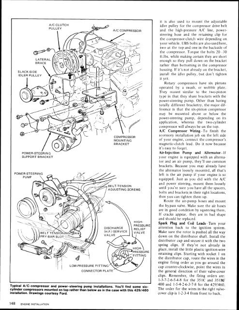
SUPPORT BRACKET<br />
I<br />
Typical A/C-compressor and power-steering pump installations. You'll find some sixcylinder<br />
compressors mounted on top rather than below as in the case with this <strong>429</strong>/460<br />
installation. Drawings courtesy <strong>Ford</strong>.<br />
it is also used to mount the adjustable<br />
idler pulley for the compressor drive belt<br />
and the high-pressure A/C line. powersteering<br />
hose and the retaining clip for<br />
the compressor-clutch wire depending on<br />
your vehicle. UBS bolts are also used here.<br />
two at the top and one in the backside <strong>of</strong><br />
the compressor. <strong>To</strong>rque the bolts 20-30<br />
ft.lbs. while making certain they are short<br />
, enough so they pull down on the bracket<br />
rather than bottoming in the compressor<br />
housing. If it's not already on the bracket,<br />
install the idler pulley, but don't tighten<br />
it yet.<br />
Rotary compressors have six pistons<br />
operated by a swash. or wobble plate.<br />
They mount similar to the two-piston<br />
type in that they share brackets with the<br />
power-steering pump. Other than having<br />
totally different bracketry, the major difference<br />
is that the six-piston compressor<br />
may be mounted above or below the<br />
power-steering pump, depending on its<br />
application, whereas the two-cylinder<br />
compressor will always be on the top.<br />
A/C Compressor Wiring-<strong>To</strong> finish the<br />
accessory installation job on the left side<br />
<strong>of</strong> your engine, connect the compressor's<br />
magnetic-clutch lead. Do it now because<br />
it's easy to forget.<br />
Air-Injection Pump and Alternator-If<br />
your engine is equipped with an alternator<br />
and an air pump, they'll use common<br />
brackets. Because you may already have<br />
the alternator loosely mounted, all that's<br />
left is the air pump if your engine is so<br />
equipped. Just as you did with the A/C<br />
and power steering, mount them loosely<br />
until you're sure you have all the spacers,<br />
bolts and bracketsin their right locations,<br />
then you can tighten them up.<br />
Route the air-pump hoses and mount<br />
the bypass valve. Make sure the air hoses<br />
are in good condition by squeering them.<br />
If cracks appear. they are in bad shape<br />
and should be replaced.<br />
I<br />
Spark Plug and Coil Leads-Turn your<br />
attention back to the ignition system.<br />
Make sure the rotor is pushed all the way<br />
down on the distributor shaft. Install the<br />
distributor cap and secure it with the two<br />
spring clips. If they're not already in<br />
place, install the little plastic ignition-wire<br />
retaining clips. Starting with socket 1 on<br />
the distributor cap, route the wires in the<br />
engine firing order as you go around the<br />
cap counter-clockwise, point the wires in<br />
the general direction <strong>of</strong> their valve-cover<br />
clips. Remember, the firing orders are:<br />
1-3-7-2-6-5-4-8 for the <strong>351C</strong> and <strong>351M</strong>/<br />
<strong>400</strong> and 1-54-2-6-3-7-8 for the <strong>429</strong>1460.<br />
The order for the wires in the right valvecover<br />
clip is 1-2-3-4 from front to back.


