

How To Rebuild Your Ford V-8 351C-351M-400-429-460.pdf - Index of
How To Rebuild Your Ford V-8 351C-351M-400-429-460.pdf - Index of
How To Rebuild Your Ford V-8 351C-351M-400-429-460.pdf - Index of

Create successful ePaper yourself
Turn your PDF publications into a flip-book with our unique Google optimized e-Paper software.
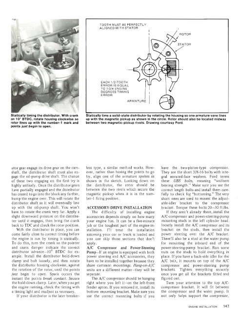
TOOTH MUST BE PERFECTLY<br />
ALIGNED WITH STATOR<br />
I<br />
EACH 112-TOOTH<br />
ERROR IS EQUAL<br />
TO 7-314 ENGINE<br />
DEGREES TIMING<br />
ERROR<br />
ARMATURE<br />
Statically timing the distributor. With crank<br />
on 10" BTDC, rotate housing clockwise so<br />
rotor lines up with the number-1 mark and<br />
points just begin to open.<br />
Statically time a solid-state distributor by rotating the housing so one armature vane lines<br />
up with the magnetic pickup as shown in the circle. Rotor should also be located midway<br />
between two magnetic-pickup rivets. Drawing courtesy <strong>Ford</strong>.<br />
utor gear engage its drive gear on the camshaft,<br />
the distributor shaft must also engage<br />
the oil-pump drive shaft. The chance<br />
<strong>of</strong> these two engaging on the first try is<br />
highly unlikely. Once the distributor gears<br />
have partially engaged and the distributor<br />
has ceased to go into the block any farther,<br />
bump the engine over. This will rotate the<br />
distributor shaft so it will eventually line<br />
up with the oil-pump shaft. You won't<br />
have to rotate the crank very far. Apply a<br />
slight downward pressure on the distributor<br />
until it engages, then bring the crank<br />
back to TDC and check the rotor position.<br />
With the distributor in place, you can<br />
come fairly close to correct timing before<br />
the engine is run by timing it statically.<br />
<strong>To</strong> do this, turn the crank so the pointer<br />
and crank damper indicate the correct<br />
distributor advance-10" BTDC for example.<br />
Install the distributor hold-down<br />
clamp and bolt loosely, and then rotate<br />
the distributor housing clockwise, against<br />
the rotation <strong>of</strong> the rotor, until the points<br />
just begin to open. Spark occurs the<br />
instant the points break contact. Secure<br />
the hold-down clamp. Later, when you get<br />
the engine running, check the timing with<br />
a timing light and readjust as necessary.<br />
If your distributor is the later breaker-<br />
less type, a similar method works. <strong>How</strong>ever,<br />
rather than having the points to go<br />
by, align one <strong>of</strong> the armature spokes as<br />
shown in the sketch. Looking down on<br />
the distributor, the rotor should be<br />
between the two rivets which secure the<br />
magnetic pickup when it is in the number-1<br />
firing position.<br />
ACCESSORY-DRIVE INSTALLATION<br />
The difficulty <strong>of</strong> installing engine<br />
accessories depends simply on how many<br />
your engine has. It can be a five-minute<br />
job or the toughest part <strong>of</strong> the engine installation.<br />
I'll treat the installation<br />
assuming your car or truck is loaded and<br />
you can skip those sections that don't<br />
apply.<br />
A/C Compressor and Power-Steering<br />
Pump-If an engine is equipped with both<br />
power steering and A/C accessories, they<br />
have to be installed together because they<br />
share common mountings. Hang-on-A/C<br />
units are a different matter-they will be<br />
separate.<br />
The A/C compressor should be hanging<br />
right where you left it-on the left-front<br />
fender apron. If you removed it, install its<br />
bottom mounting bracket. Make sure you<br />
use the correct mounting bolts if you<br />
have the two-piston-type compressor.<br />
They are the short 3/8-16 bolts with integral<br />
serrated-face washers. <strong>Ford</strong> terms<br />
these UBS bolts, meaning "uniform<br />
bearing strength." Make sure you use the<br />
correct length bolts and install them carefully<br />
to check f<strong>of</strong> "bottoming." The very<br />
short ones are used to mount the adjustable-idler<br />
bracket to the compressor<br />
bracket. <strong>To</strong>rque these bolts 20-30 ft.lbs.<br />
If they aren't already there, install the<br />
A/C-compressor and power-steering-pump<br />
mounting studs in the left cylinder head.<br />
loosely install the A/C compressor and its<br />
bracket on the studs, then install the<br />
power steering over the A/C bracket.<br />
There'll also be a stud at the water pump<br />
for mounting the inboard end <strong>of</strong> the<br />
power-steering-pump bracket. Run some<br />
nuts on the studs to hold everything in<br />
place. If you have a back-side idler for the<br />
A/C belt, it mounts on top <strong>of</strong> the A/C<br />
compressor and power-steering pump<br />
brackets. Tighten everything securely<br />
once you get all the brackets fitted and<br />
figured out.<br />
Turn your attention to the top A/Ccompressor<br />
bracket. It will fit between<br />
the compressor and the water pump. It<br />
not only helps support the compressor,


