

How To Rebuild Your Ford V-8 351C-351M-400-429-460.pdf - Index of
How To Rebuild Your Ford V-8 351C-351M-400-429-460.pdf - Index of
How To Rebuild Your Ford V-8 351C-351M-400-429-460.pdf - Index of

Create successful ePaper yourself
Turn your PDF publications into a flip-book with our unique Google optimized e-Paper software.
anything from a cardboard box to a piece<br />
<strong>of</strong> lath with 16 holes drilled in it.<br />
CLEANUP AND INSPECTION<br />
Scrape, Scrape, Scrape-Time for the old<br />
gasket scraper and elbow grease again. As<br />
you probably found when scraping your<br />
block deck surfaces, head gaskets seem to<br />
have "grown to" the metal. If you had<br />
your heads hot-tanked, the job will be<br />
much easier. Clean all gasket surfaces,<br />
the head-gasket, intake-manifold and<br />
rocker-arm-cover sealing surfaces <strong>of</strong> all<br />
old gasket material. Using a round file,<br />
clean the head-to-block water passages<br />
<strong>of</strong> all deposits.<br />
It's time to misuse a screwdriver or a<br />
small chisel. Scrape the carbon deposits<br />
from the combustion chambers and exhaust<br />
and intake ports. After the heavy<br />
work is done, finish the job with a wire<br />
brush. This will put a light polish on the<br />
surface so you can spot any cracks which<br />
may have developed in the combustion<br />
chambers, particularly around the valveseat<br />
area. If you do find cracks in any <strong>of</strong><br />
these areas, don't junk the head just yet.<br />
Take it to your engine machinist to see<br />
if it can be repaired by pinning. If it<br />
can't, then it's junk. Even though it may<br />
be repairable by welding, chances are this<br />
cost will exceed the cost <strong>of</strong> replacement.<br />
Head-Surface Flatness-Because cylinder<br />
heads are subjected to extreme heat, combustion<br />
and compression loads and are<br />
structurally weak compared to an engine<br />
block, they are susceptible to warping, as<br />
well as cracking. Excessive mismatch between<br />
block and deck surfaces causes<br />
combustion or coolant leakages, consequently<br />
those surfacesmust beflat. Check<br />
the head-gasket surfaces with a straightedge<br />
and feeler gages. Set the straightedge<br />
lengthwise and diagonally across the<br />
head in both directions. Measure clearances<br />
which appear between the head and<br />
the straight-edge with your feeler gages.<br />
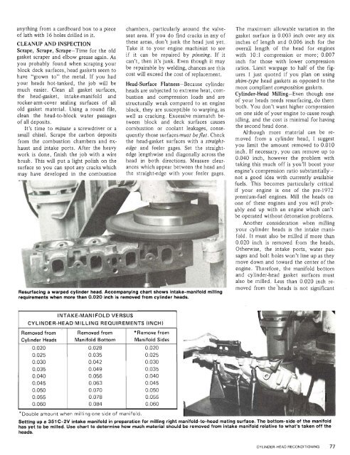
Resurfacing a warped cylinder head. Accompanying chart shows intake-manifold milling<br />
requirements when more than 0.020 inch is removed from cylinder heads.<br />
The maximum allowable variation in the<br />
gasket surface is 0.003 inch over any six<br />
inches <strong>of</strong> length and 0.006 inch for the<br />
overall length <strong>of</strong> the head for engines<br />
with 10:l compression or more; 0.007<br />
inch for those with lower compression<br />
ratios. .Limit warpage to half <strong>of</strong> the figures<br />
I just quoted if you plan on using<br />
shim-type head gaskets as opposed to the<br />
more compliant composition gaskets.<br />
Cylinder-Head Milling-Even though one<br />
<strong>of</strong> your heads needs resurfacing, do them<br />
both. You don't want higher compression<br />
on one side <strong>of</strong> your engine to cause rough<br />
idling, and the cost is minimal for having<br />
the second head done.<br />
Although more material can be removed<br />
from a cylinder head, I suggest<br />
you limit the amount removed to 0.010<br />
inch. If necessary, you can remove up to<br />
0.040 inch, however the problem with<br />
taking this much <strong>of</strong>f is you'll boost your<br />
engine's compression ratio substantiallynot<br />
a good idea with currently available<br />
fuels. This becomes particularly critical<br />
if your engine is one <strong>of</strong> the pre-1972<br />
premium-fuel engines. Mill the heads on<br />
one <strong>of</strong> these engines and you will probably<br />
end up with an engine which can't<br />
be operated without detonation problems.<br />
Another consideration when milling<br />
your cylinder heads is the intake manifold.<br />
It must also be milled if more than<br />
0.020 inch is removed from the heads.<br />
Otherwise, the intake ports, water passages<br />
and bolt holes won't line up as they<br />
move down and toward the center <strong>of</strong> the<br />
engine. Therefore, the manifold bottom<br />
and cylinder-head gasket surfaces must<br />
also be milled. Less than 0.020 inch removed<br />
from the3heads is not significant<br />
INTAKE-MAN1 COLD VERSUS<br />
CYLINDER-HEAD MILLING REQUIREMENTS (INCH)<br />
Removed from<br />
Cylinder Heads<br />
0.020<br />
0.025<br />
0.030<br />
0.035<br />
0.040<br />
0.045<br />
0.050<br />
0.055<br />
0.060<br />
Removed from<br />
Manifold Bottom<br />
0.028<br />
0.035<br />
0.042<br />
0.049<br />
0.056<br />
0.063<br />
0.070<br />
0.078<br />
0.084<br />
*Remove from<br />
Manifold Sides<br />
0.020<br />
0.025<br />
0.030<br />
0.035<br />
0.040<br />
0.045<br />
0.050<br />
0.055<br />
0.060<br />
uble amount when milling one side <strong>of</strong> manifold.<br />
Setting up a 351 C-2V intake manifold in preparation for milling right manifold-to-head mating surface. The bottom-side <strong>of</strong> the manifold<br />
has yet to be milled. Use chart to determine how much material should be removed from intake manifold relative to what's taken <strong>of</strong>f the<br />
heads.<br />
CYLINDER-HEAD RECONDITIONING 77


