

How To Rebuild Your Ford V-8 351C-351M-400-429-460.pdf - Index of
How To Rebuild Your Ford V-8 351C-351M-400-429-460.pdf - Index of
How To Rebuild Your Ford V-8 351C-351M-400-429-460.pdf - Index of

You also want an ePaper? Increase the reach of your titles
YUMPU automatically turns print PDFs into web optimized ePapers that Google loves.
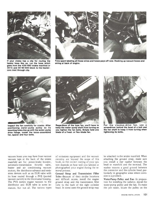
If your choke has a clip for routing the<br />
heater hose like so, run the hose whlch<br />
goes from the <strong>429</strong>/460 Intake manifold or<br />
351 C and 351 M/<strong>400</strong> block to the heatercore<br />
inlet through clip.<br />
L<br />
Time spent labellng all those wires and hose s pays <strong>of</strong>f now. Hooklng up vacuum hoses and<br />
wiring at back <strong>of</strong> engine.<br />
Inspect the fan carefully for cracks. After<br />
positioning water-pump pulley so its<br />
mounting holes line up with the water-pump<br />
drive flange, install the loose-assembled<br />
fan, spacer and four bolts.<br />
Regardless , .,,, ., ,n,<br />
you'll have to<br />
keep the water-pump shaft from turning as<br />
you tighten the fan bolts. Simply hold one<br />
blade <strong>of</strong> a fixed- or flex-blade fan.<br />
screwdriver behind the head <strong>of</strong> a bolt and<br />
the fan shaft to keep it from turning when<br />
tightening its bolts..<br />
vacuum hoses you may have from various<br />
vacuum taps at the back <strong>of</strong> the intake<br />
manifold are for: power-brake booster,<br />
automatic-transmission throttle valve,<br />
heater and air conditioning vacuum<br />
motors, the distributor-advance and emissions<br />
devices such as an EGR valve with<br />
its hose routed through a PVS (ported<br />
vacuum switch) in the thermostat housing.<br />
The PVS meters engine vacuum to the<br />
distributor and EGR valve in some instances,<br />
but not all. The various types<br />
<strong>of</strong> emissions equipment and the vacuum<br />
circuitry are beyond the scope <strong>of</strong> this<br />
book, so the correct routing <strong>of</strong> your system<br />
depends on how well you labeled or<br />
photographed your engine during the removal<br />
process.<br />
Ground Strap and Transmission Filler<br />
Tube-Because <strong>of</strong> their similar locations<br />
and difficult access, install the engine<br />
ground strap and the transmission filler<br />
tube to the back <strong>of</strong> the right cylinder<br />
head. In some cases the ground strap may<br />
be attached to the intake manifold. When<br />
attaching the ground strap, make sure<br />
you install a star washer between the<br />
head or manifold and the terminal. The<br />
washer ensures a good ground between<br />
the connector and the cylinder head, particularly<br />
in geographic areas where corrosion<br />
is a problem.<br />
Water-Pump Pulley and Fan-In preparation<br />
for installing the radiator, install the<br />
water-pump pulley and the fan. <strong>To</strong> make<br />
the job easier, locate the pulley on the


