After you've cleaned out the head- and main-bearing-bolt threads, go after the water passages. Remove any loose rust, deposits and core sand. Pay particular attention to the passages connecting the cylinder heads to the block to ensure good coolant flow to the heads. A round or rat-tail file works well for this iob. but be careful <strong>of</strong> the head-gasket surtaces. A gouge in the wrong place can cause aheadgasket leak. Give the same treatment to She cylinder heads During all this scrubbing, scraping and general clean-up, compressed air for forcing dirt out <strong>of</strong> hard-to-get-at areas and for drying the block will be a definite help. Controlling moisture becomes more <strong>of</strong> a problem as you recondition more and more <strong>of</strong> the parts. Bearing-bore surfaces, cylinder bores, valve seats and any other machined surface will rust from humidity in the air. So, prevent this by coating the machined surfaces with a water-dispersant oil after cleaning or machining. Several brands are available from your local store, such as WD-40 and CRC. They'll do the job with a lot less fuss and mess than a squirt can <strong>of</strong> motor oil. Whatever you use, don't leave any freshly machined surface unoiled or it will rust for sure CYLINDER-BLOCK FINAL INSPECTION & RECONDITIONING Inspecting your engine block to determine what must be done to restore it to tip-top condition is your first reconditioning step. <strong>To</strong> perform a satisfactory inspection job, you'll need 3-4.-inch outside and inside micrometers, a very straight edge, and feeler gages. A set <strong>of</strong> telescoping gages will eliminate the need for the inside mikes. You may not need the straight edge if the head-gasket checked out OK. If the old gaskets didn't leak, the new ones won't either, if they are installed correctly. Checking Bore Wear-Cylinder-bore wear dictates whether your block needs boring or just honing. This, in turn, largely determines whether you have to install new pistons-no small investment. You can check bore wear three ways. The best is with a dial-bore gage, but you may not have one, so let's look at the remaining methods. Next in order <strong>of</strong> accuracy is the inside micrometer or telescopic gage and an outside mike. The last method involves using a piston ring and feeler gages to compare end-gaps at different positions in the bore. All <strong>of</strong> these methods will tell you what each bore's taper is. Bore Taper-Cylinder walls don't wear the same from top to bottom. A bore wears WEAR (IN.) CYLINDER-WALL WEAR VS OPERATING TEWIPERATURE 60-HOUR TEST TEMPERATURE (OF) Why you should always use a thermostat. Bore wear increases dramatically as engine operating temperature goes down, particularly when it's less than 180°F (82°C). Data courtesy Continental Motors. more at the top, with wear decreasing toward the bottom. Virtually no wear occurs in the lower portion <strong>of</strong> a bore. Load exerted by the top compression ring against its cylinder wall during the power stroke decreases rapidly as the piston travels down from the top <strong>of</strong> its stroke. This varying load is the major cause <strong>of</strong> bore taper. In addition, the bottom <strong>of</strong> a bore which has the maill function <strong>of</strong> stabilizing the piston is better lubricated and receives little wear. This is shown by the shiny upper part <strong>of</strong> a bore-while the bottom retains its original cross-hatch pattern. Measuring Taper-Because a bore wears little at its bottom, if you compare the distance across the bore at the bottom versus that at the top, just below the ridge, you can determine its taper. Also, bores don't' wear evenly all the way around, nor do all cylinders wear the same. Therefore, when measuring a bore, measure it parallel to the centerline <strong>of</strong> the engine, then at 90" to the centerline. Take a couple <strong>of</strong> measurements in between and use the highest figure. It will determine what and how much must be done to that bore to restore it. Because it's not practical to treat each cylinder separately, you'll have to pinpoint the one with the worst taper and let it be the gage <strong>of</strong> what must be done to the remaining seven cylinders. One exception is when one cylinder is damaged or worn beyond the point where it can't be re- stored by boring, and the other cylinders are OK. In this case, it may be less expensive to have the cylinder sleeved rather than junking your block and buying another one. When checking bore wear you'll notice the end cylinders have the most wear. The reason is the end cylinders operate cooler than the others, causing more wear. Most wear is concentrated on the side <strong>of</strong> the cylinder walls closest to the ends <strong>of</strong> the cylinder block in cylinders 1, 4, 5 and 8. A quick way to verify what I've said is to compare the ridges in each bore by feeling them with your finger tip, particularly the variation in thickness <strong>of</strong> the ridges in the end cylinders. Because <strong>of</strong> the wear pattern in the end cylinders, wear measured parallel to the engine centerline will exceed that measured 90" to the centerline. Due to uneven bore wear, taper, or the difference between maximum and minimum bore wear, measuring may not provide a final figure as to how much a cylinder must be bored to clean it up-to expose new metal the full length <strong>of</strong> a bore. The reason is, uneven wear shifts a bore's centerline in the direction <strong>of</strong> the wear. <strong>To</strong> restore a cylinder to its original centerline usually requires removing more metal than indicated by its taper. As a result, final bore-size determination is made at the time <strong>of</strong> boring. If a cylinder bore does not clean up at 0.010 inch oversize, the machinist has to bore to I BLOCK RECONDI.rIONING 53
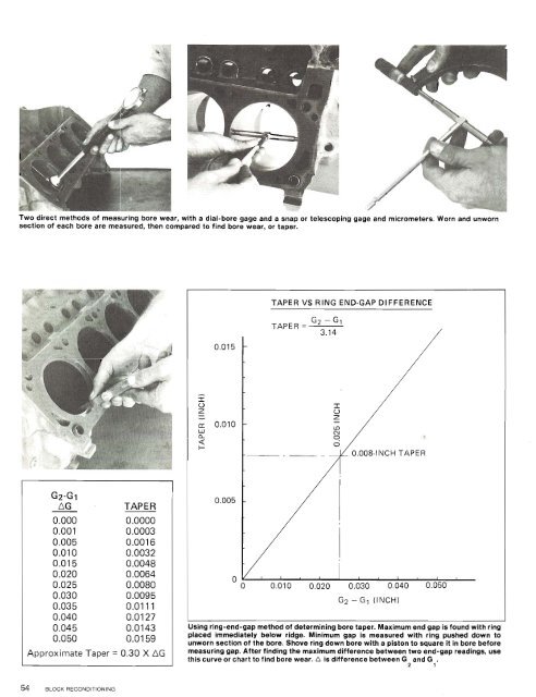
Two direct methods <strong>of</strong> measuring bore wear, with a dial-bore gage and a snap or telescoping gage and micrometers. Worn and unworn section <strong>of</strong> each bore are measured, then compared to find bore wear, or taper. TAPER VS RING END-GAP DIFFERENCE TAPER = G2 - G1 3.14 G2-GI AG . TAPER 0.000 0.0000 0.001 0.0003 0.005 0.0016 0.010 0.0032 0.015 0.0048 0.020 0.0064 0.025 0.0080 0.030 0.0095 0.035 0.01 11 0.040 0.0127 0.045 0.0143 0.050 0.0159 Approximate Taper = 0.30 X AG Using ring-end-gap methodf determining bore taper~aximum end gap is found with ring placed immediately below ridge. Minimum gap Is measured with ring pushed down to unworn section <strong>of</strong> the bore. Shove ring down bore with a piston to square it in bore before measuring gap. After flnding the maximum difference between two end-gap readings, use this curve or chart to find bore wear. A is difference between G and G . 2 1
- Page 1 and 2:
HPBooks How to find out what needs
- Page 3: Introduction This book deals with r
- Page 6 and 7: DIAGNOSIS home and dumping the "ins
- Page 8 and 9: A complete, high-quality tune-up ki
- Page 10 and 11: may be causing the problem at this
- Page 12 and 13: ect, particularly if there appears
- Page 14 and 15: To ensure that your hood will fit a
- Page 16 and 17: Radlators can be heavy like this bi
- Page 18 and 19: emove the compressor and have a sys
- Page 20 and 21: ENGINE REMOVAL 19 - i When jacking
- Page 22 and 23: ENGINE REMOVAL 21 After starter-mot
- Page 24 and 25: get on with the physical makeup of
- Page 26 and 27: Cylinder-block, cranksharr an0 cy~~
- Page 28 and 29: When sifting through your local scr
- Page 30 and 31: 351C Boss, '71 CJ, HO '72-74 4V CYL
- Page 32 and 33: I I Pop-up '71 351C Boss piston and
- Page 34 and 35: pushrod-guided aspect comes in. Thi
- Page 36 and 37: PARTS 35 Compression ratio is deter
- Page 38 and 39: 4291460-Standard 429 and 460 cylind
- Page 40 and 41: Tearing down your engine is the fir
- Page 42 and 43: Remove engine-lifting lugs and exha
- Page 44 and 45: You'll need a puller to remove the
- Page 46 and 47: cam sprocket and chain, and then th
- Page 48 and 49: them; they'll tell you a story. Bea
- Page 50 and 51: If you are removing your cam bearin
- Page 52 and 53: 5 Inspecting and Reconditioning the
- Page 56 and 57: 0.020 inch, the next available over
- Page 58 and 59: Checking deck-surface flatness with
- Page 60 and 61: Cross-hatch pattern of a freshly ho
- Page 62 and 63: If you don't have a snap gage, here
- Page 64 and 65: Using grease and some machined roun
- Page 66 and 67: while your micrometer is handy, do
- Page 68 and 69: When measuring piston diameter, do
- Page 70 and 71: Using a piston ring and a feeler ga
- Page 72 and 73: Five- and four-plate timing chains
- Page 74 and 75: New oil-pump drive shaft above and
- Page 76 and 77: CYLINDER-HEAD RECONDITIONING 75 If
- Page 78 and 79: anything from a cardboard box to a
- Page 80 and 81: CYLINDER-HEAD RECONDITIONING 79 . .
- Page 82 and 83: The K-Line bronze valve-guide inser
- Page 84 and 85: will be sealed the first time the v
- Page 86 and 87: or 68 lbs. in this case. If a sprin
- Page 88 and 89: Uslng a short sectlon of wlre cut a
- Page 90 and 91: Except for rocker arms and fulcrums
- Page 92 and 93: This is the part of engine building
- Page 94 and 95: .,., ....., ,. ,., .,. . .,. differ
- Page 96 and 97: If you are installing a new or regr
- Page 98 and 99: BEARING-CLEARANCE CHECKING ROTATING
- Page 100 and 101: Large socket and brass hammer being
- Page 102 and 103: ENGINE ASSEMBLY 101 in the caps, po
- Page 104 and 105:
Section of an oil-ring assembly. Le
- Page 106 and 107:
Piston-and-rod assemblies lined up
- Page 108 and 109:
A simple check to make sure pistons
- Page 110 and 111:
metal cover. You can tap the seal i
- Page 112 and 113:
Install water pump before the seale
- Page 114 and 115:
Carefully fit oil pan on block and
- Page 116 and 117:
Yes, 429/460 head bolts are differe
- Page 118 and 119:
Installing early stamped-steel rock
- Page 120 and 121:
lnstalllng the Intake-manifold end
- Page 122 and 123:
ENGINE ASSEMBLY 121 With the gasket
- Page 124 and 125:
12-15 ft. lbs. 4291460 has a horizo
- Page 126 and 127:
LUBRICATING WICK- Centrifugal weigh
- Page 128 and 129:
- 1 I Magnetic-pickup retaining cli
- Page 130 and 131:
I - Real-life removal of top distrl
- Page 132 and 133:
- Slide gear on the shaft while kee
- Page 134 and 135:
housing with the remaining screw. I
- Page 136 and 137:
Begin carburetor teardown by removi
- Page 138 and 139:
You're now ready for the last big o
- Page 140 and 141:
Install standard-transmission front
- Page 142 and 143:
spots, creating little bumps on the
- Page 144 and 145:
4 - -- - - - - - \ 2 ~ ---- I nrr:
- Page 146 and 147:
_- PASSENGER CAR KICKDOWN ROD 10-25
- Page 148 and 149:
TOOTH MUST BE PERFECTLY ALIGNED WIT
- Page 150 and 151:
P'. Object here is to ger rnar rlrs
- Page 152 and 153:
If your choke has a clip for routin
- Page 154 and 155:
- R ENGINE INSTALLATION 153 ~ Cross
- Page 156 and 157:
starts turning and the rest of the
- Page 158 and 159:
After putting a few hundred miles o
- Page 160 and 161:
Index A AIC compressor 152- 153 bac
- Page 162:
HP AUTO BOOKS MAKE YOU THE PRO! I H