

How To Rebuild Your Ford V-8 351C-351M-400-429-460.pdf - Index of
How To Rebuild Your Ford V-8 351C-351M-400-429-460.pdf - Index of
How To Rebuild Your Ford V-8 351C-351M-400-429-460.pdf - Index of

Create successful ePaper yourself
Turn your PDF publications into a flip-book with our unique Google optimized e-Paper software.
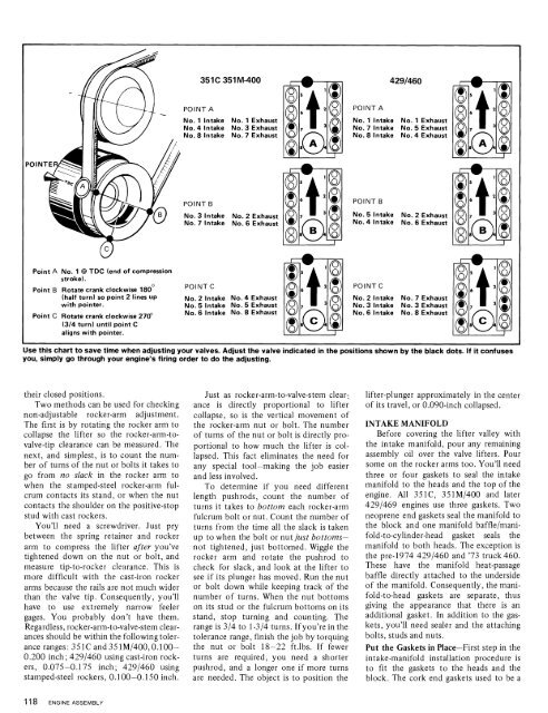
351 C 351 M-<strong>400</strong><br />
No. 8 Intake No. 7 Exhaust No. 8 Intake No. 4 Exhaust<br />
No. 4 Intake<br />
No. 6 Exhaust<br />
Point B Rotate crank clockwise 180<br />
(half turn) so point 2 lines up No. 2 Intake No. 4 Exhaust No. 2 Intake No. 7 Exhaust<br />
with pointer.<br />
No. 5 Intake No. 5 Exhaust<br />
No. 6 Intake No. 8 Exhaust No. 6 Intake No. 8 Exhaust<br />
Use this chart to save time when adjusting your valves. Adjust the valve indicated in the positions shown by the black dots. If it confuses<br />
you, simply go through your engine's firing order to do the adjusting.<br />
their closed positions.<br />
Two methods can be used for checking<br />
non-adjustable rocker-arm adjustment.<br />
The first is by rotating the rocker arm to<br />
collapse the lifter so the rocker-arm-tovalve-tip<br />
clearance can be measured. The<br />
next, and simplest, is to count the number<br />
<strong>of</strong> turns <strong>of</strong> the nut or bolts it takes to<br />
go from no slack in the rocker arm to<br />
when the stamped-steel rocker-arm fulcrum<br />
contacts its stand, or when the nut<br />
contacts the shoulder on the positive-stop<br />
stud with cast rockers.<br />
You'll need a screwdriver. Just pry<br />
between the spring retainer and rocker<br />
arm to compress the lifter after you've<br />
tightened down on the nut or bolt, and<br />
measure tip-to-rocker clearance. This is<br />
more difficult with the cast-iron rocker<br />
arms because the rails are not much wider<br />
than the valve tip. Consequently, you'll<br />
have to use extremely narrow feeler<br />
gages. You probably don't have them.<br />
Regardless, rocker-arm-to-valve-stem clearances<br />
should be within the following tolerance<br />
ranges: <strong>351C</strong> and<strong>351M</strong>/<strong>400</strong>,0.100-<br />
0.200 inch; <strong>429</strong>1460 using cast-iron rockers,<br />
0.075-0.175 inch; <strong>429</strong>1460 using<br />
stamped-steel rockers, 0.100-0.1 50 inch.<br />
Just as rocker-arm-to-valve-stem clearance<br />
is directly proportional to lifter<br />
collapse, so is the vertical movement <strong>of</strong><br />
the rocker-arm nut or bolt. The number<br />
<strong>of</strong> turns <strong>of</strong> the nut or bolt is directly proportional<br />
to how much the lifter is collapsed.<br />
This fact eliminates the need for<br />
any special tool-making the job easier<br />
and less involved.<br />
<strong>To</strong> determine if you need different<br />
length pushrods, count the number <strong>of</strong><br />
turns it takes to bottom each rocker-arm<br />
fulcrum bolt or nut. Count the number <strong>of</strong><br />
turns from the time all the slack is taken<br />
up to when the bolt or nut just bottomsnot<br />
tightened, just bottomed. Wiggle the<br />
rocker arm and rotate the pushrod to<br />
check for slack, and look at the lifter to<br />
see if its plunger has moved. Run the nut<br />
or bolt down while keeping track <strong>of</strong> the<br />
number <strong>of</strong> turns. When the nut bottoms<br />
on its stud or the fulcrum bottoms on its<br />
stand, stop turning and counting. The<br />
range is 314 to 1-314 turns. If you're in the<br />
tolerance range, finish the job by torquing<br />
the nut or bolt 18-22 ft.lbs. If fewer<br />
turns are required, you need a shorter<br />
pushrod, and a longer one if more turns<br />
are needed. The object is to position the<br />
lifter-plunger approximately in the center<br />
<strong>of</strong> its travel, or 0.090-inch collapsed.<br />
INTAKE MANIFOLD<br />
Before covering the lifter valley with<br />
the intake manifold, pour any remaining<br />
assembly oil over the valve lifters. Pour<br />
some on the rocker arms too. You'll need<br />
three or four gaskets to seal the intake<br />
manifold to the heads and the top <strong>of</strong> the<br />
engine. All <strong>351C</strong>, <strong>351M</strong>1<strong>400</strong> and later<br />
<strong>429</strong>1469 engines use three gaskets. Two<br />
neoprene end gaskets seal the manifold to<br />
the block and one manifold bafflelmanifold-to-cylinder-head<br />
gasket seals the<br />
manifold to both heads. The exception is<br />
the pre-1974 <strong>429</strong>1460 and '73 truck 460.<br />
These have the manifold heat-passage<br />
baffle directly attached to the underside<br />
<strong>of</strong> the manifold. Consequently, the manifold-to-head<br />
gaskets are separate, thus<br />
giving the appearance that there is an<br />
additional gasket. In addition to the gaskets,<br />
you'll need sealer and the attaching<br />
bolts, studs and nuts.<br />
Put the Gaskets in Place-First step in the<br />
intake-manifold installation procedure is<br />
to fit the gaskets to the heads and the<br />
block. The cork end gaskets used to be a


