

How To Rebuild Your Ford V-8 351C-351M-400-429-460.pdf - Index of
How To Rebuild Your Ford V-8 351C-351M-400-429-460.pdf - Index of
How To Rebuild Your Ford V-8 351C-351M-400-429-460.pdf - Index of

Create successful ePaper yourself
Turn your PDF publications into a flip-book with our unique Google optimized e-Paper software.
The K-Line bronze valve-guide insert is<br />
installed in a similar manner as the castiron<br />
insert. The existing guide is reamed<br />
oversize and the thin-wall insert-approximately<br />
0.060-inch thick-is installed<br />
kith a special driver. Once in place, the<br />
excess material is trimmed <strong>of</strong>f. The guide<br />
is expanded and reamed to size using the<br />
original valve seat as a pilot to prevent<br />
tilting the valve guide. This should be<br />
done when reaming any type <strong>of</strong> guide.<br />
VALVE INSPECTION AND<br />
RECONDITIONING<br />
After getting your valve guides in<br />
shape, next on the list are the valves<br />
themselves. You should have already<br />
checked them for obvious damage such as<br />
burnt heads and excessively worn tips,<br />
particularly if your engine is the pre-'72<br />
<strong>429</strong> with rail rocker arms.<br />
Measure Valve-Stem Wear-3 51 C, 351 MI<br />
<strong>400</strong> and <strong>429</strong>1460 engines use valves with<br />
nominal 11132-inch stem diameters. More<br />
precisely, 351 C and <strong>351M</strong>1<strong>400</strong> valve-stem<br />
diameters are 0.3416-0.3423 inch for<br />
the intakes and 0.341 1-0.3418 inch for<br />
the exhausts. <strong>429</strong>1460 intake and exhaustvalve<br />
stems are the same diameter at<br />
0.3416-0.3423 inch. The reason for the<br />
smaller 351 C and 351 MI<strong>400</strong> exhaustvalve<br />
stem is to provide the proper hot<br />
stem-to-guide clearance as all valve guides<br />
are reamed to the same diameter.<br />
Use the preceding figures to check for<br />
stem wear, or you can compare the worn<br />
and unworn portion <strong>of</strong> each valve stem to<br />
determine exact wear. Maximum stem<br />
wear usually occurs at the tip end <strong>of</strong> a<br />
valve. This area is easily recognizable as<br />
the shlny portion <strong>of</strong> the valve stem.<br />
There's a sharp division between it and<br />
the unworn surface. Maximum valve<br />
opening is represented by the end <strong>of</strong> the<br />
shiny surface at the tip end. This is where<br />
a valve stops in its guide at its full-open<br />
position.<br />
You'll need a- 1-inch micrometer to<br />
check valve-stem wear. Measure the stem<br />
diameters immediately above and below<br />
the maximum-wear line, then subtract to<br />
determine wear.<br />
Now that you've come up with a figure<br />
for valve-stem wear, the question is<br />
how mu'ch is acceptable Again, this depends<br />
on the service you expect from<br />
your engine after the rebuild, if and how<br />
you reconditioned the valve guides and a<br />
myriad <strong>of</strong> other questions that makes<br />
arriving at an exact wear figure impossible.<br />
<strong>How</strong>ever, concentrating on desired<br />
service and the type <strong>of</strong> reconditioning<br />
you did on your guides, you should be<br />
able to answer this question.<br />
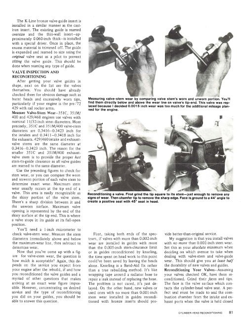
Measuring valve-stem wear by comparing valve stem's worn and unworn portion. You'll<br />
find them directly below and above the wear line on valve's tip-end. This valve was replaced<br />
because I decided 0.001 5 inch wear was too much for the additional mileage planned<br />
for the engine.<br />
Reconditionlllu ran.-. rwa. rllllu LII= tip square to Its stem-just enough to remove any<br />
signs <strong>of</strong> wear. Then chamfer tip to remove the sharp edge. Face isground to a 44' angle to<br />
create a positive seal with 45" seat in head.<br />
First, taking both ends <strong>of</strong> the spectrum,<br />
if valves with more than 0.002-inch<br />
wear are installed in guides with more<br />
than the 0.005-inch stem-clearance limit<br />
or in guides reconditioned by knurling,<br />
the time spent on head work to this point<br />
could've been saved by leaving the heads<br />
alone. Knurling is a Band-Aid fix rather<br />
than a true rebuilding method. It's like<br />
wrapping tape around a radiator hose to<br />
repair a leak instead <strong>of</strong> replacing the hose.<br />
The problem is not cured, it's just delayed.<br />
On the other hand, new valves or<br />
used ones with no more than 0.001-inch<br />
stem wear installed in guides reconditioned<br />
with bronze inserts should pro-<br />
vide better-than-original service.<br />
My suggestion is that you install valves<br />
with no more than 0.002-inch stem wear.<br />
Set this as your absolute minimum when<br />
deciding on which avenue to take when<br />
dealing with valve-stem and valve-guide<br />
wear. This should give you at least half<br />
the durability <strong>of</strong> new valves and guides.<br />
Reconditioning <strong>Your</strong> Valves-Assuming<br />
your valves checked OK, have them reconditioned.<br />
Grind their faces and tips.<br />
The face is the valve surface which contacts<br />
the cylinder-head valve seat. A perfect<br />
seal must be made to seal the combustion<br />
chamber from the intake and exhaust<br />
ports when the valve is held closed


