

How To Rebuild Your Ford V-8 351C-351M-400-429-460.pdf - Index of
How To Rebuild Your Ford V-8 351C-351M-400-429-460.pdf - Index of
How To Rebuild Your Ford V-8 351C-351M-400-429-460.pdf - Index of

Create successful ePaper yourself
Turn your PDF publications into a flip-book with our unique Google optimized e-Paper software.
If you are installing a new or reground<br />
camshaft, remove drive pin from old<br />
camshaft before turning it in as a core.<br />
Replacement cams usually don't Include<br />
the pin. Remove yours by clamping on it<br />
with Vise-Grips and working it out.<br />
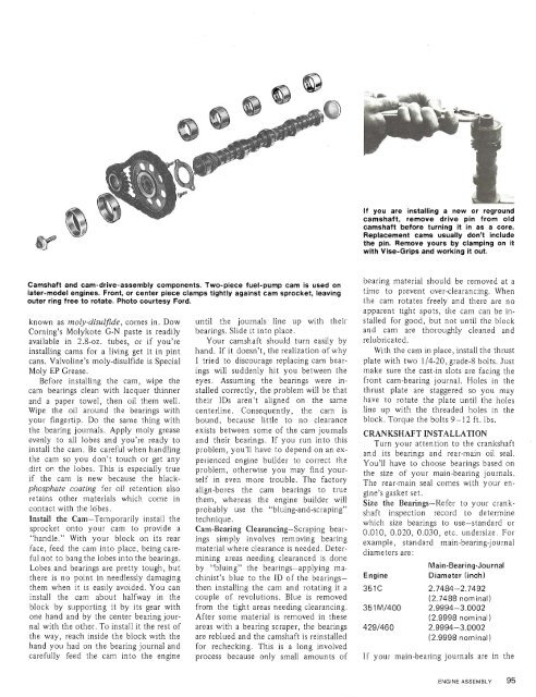
Camshaft and cam-drive-assembly components. Two-piece fuel-pump cam is used on<br />
later-model engines. Front, or center piece clamps tightly against cam sprocket, leaving<br />
outer ring free to rotate. Photo courtesy <strong>Ford</strong>.<br />
known as moly-disulfide, comes in. Dow<br />
Corning's Molykote G-N paste is readily<br />
available in 2.8-oz. tubes, or if you're<br />
installing cams for a living get it in pint<br />
cans. Valvoline's moly-disulfide is Special<br />
Moly EP Grease.<br />
Before installing the cam, wipe the<br />
cam bearings clean with lacquer thinner<br />
and a paper towel, then oil them well.<br />
Wipe the oil around the bearings with<br />
your fingertip. Do the same thing with<br />
the bearing journals. Apply moly grease<br />
evenly to all lobes and you're ready to<br />
install the cam. Be careful when handling<br />
the cam so you don't touch or get any<br />
dirt on the lobes. This is especially true<br />
if the cam is new because the blackphosphate<br />
coating for oil retention also<br />
retains other materials which come in<br />
contact with the lobes.<br />
Install the Cam-Temporarily install the<br />
sprocket onto your cam to provide a<br />
"handle." With your block on its rear<br />
face, feed the cam into place, being careful<br />
not to bang the lobes into the bearings.<br />
Lobes and bearings are pretty tough, but<br />
there is no point in needlessly damaging<br />
them when it is easily avoided. You can<br />
install the cam about halfway in the<br />
block by supporting it by its gear with<br />
one hand and by the center bearing journal<br />
with the other. <strong>To</strong> install it the rest <strong>of</strong><br />
the way, reach inside the block with the<br />
hand you had on the bearing journal and<br />
carefully feed the cam into the engine<br />
until the journals line up with their<br />
bearings. Slide it into place.<br />
<strong>Your</strong> camshaft should turn easily by<br />
hand. If it doesn't, the realization <strong>of</strong> why<br />
I tried to discourage replacing cam bearings<br />
will suddenly hit you between the<br />
eyes. Assuming the bearings were installed<br />
correctly, the problem will be that<br />
their IDS aren't aligned on the same<br />
centerline. Consequently, the cam is<br />
bound, because little to no clearance<br />
exists between some <strong>of</strong> the cam journals<br />
and their bearings. If you run into this<br />
problem, you'll have to depend on an experienced<br />
engine builder to correct the<br />
problem, otherwise you may find yourself<br />
in even more trouble. The factory<br />
align-bores the cam bearings to true<br />
them, whereas the engine builder will<br />
probably use the "bluing-and-scraping"<br />
technique.<br />
Cam-Bearing Clearancing-Scraping bearings<br />
simply involves removing bearing<br />
material where clearance is needed. Determining<br />
areas needing clearanced is done<br />
by "bluing" the bearings-applying machinist's<br />
blue to the ID <strong>of</strong> the bearingsthen<br />
installing the cam and rotating it a<br />
couple <strong>of</strong> revolutions. Blue is removed<br />
from the tight areas needing clearancing.<br />
After some material is removed in these<br />
areas with a bearing scraper, the bearings<br />
are reblued and the camshaft is reinstalled<br />
for rechecking. This is a long involved<br />
process because only small amounts <strong>of</strong><br />
bearing material should be removed at a<br />
time to prevent over-clearancing. When<br />
the cam rotates freely and there are no<br />
apparent tight spots, the cam can be installed<br />
for good, but not until the block<br />
and cam are thoroughly cleaned and<br />
relubricated.<br />
With the cam in place, install the thrust<br />
plate with two 1/4-20, grade-8 bolts. Just<br />
make sure the cast-in slots are facing the<br />
front cam-bearing journal. Holes in the<br />
thrust plate are staggered so you may<br />
have to rotate the plate until the holes<br />
line up with the threaded holes in the<br />
block. <strong>To</strong>rque the bolts 9-12 ft. lbs.<br />
CRANKSHAFT INSTALLATION<br />
Turn your attention to the crankshaft<br />
and its bearings and rear-main oil seal.<br />
You'll have to choose bearings based on<br />
the size <strong>of</strong> your main-bearing journals.<br />
The rear-main seal comes with your engine's<br />
gasket set.<br />
Size the Bearings-Refer to your crankshaft<br />
inspection record to determine<br />
which size bearings to use-standard or<br />
0.010, 0.020, 0.030, etc. undersize. For<br />
example, standard main-bearing-journal<br />
diameters are:<br />
Main-Bearing-Journal<br />
Engine<br />
Diameter (inch)<br />
2.7484-2.7492<br />
(2.7488 nominal)<br />
2.9994-3.0002<br />
(2.9998 nominal)<br />
2.9994-3.0002<br />
(2.9998 nominal)<br />
If your main-bearing journals are in the<br />
ENGINE ASSEMBLY 95


