Tsunami - Beckman Institute Laser Resource Center
Tsunami - Beckman Institute Laser Resource Center
Tsunami - Beckman Institute Laser Resource Center
Create successful ePaper yourself
Turn your PDF publications into a flip-book with our unique Google optimized e-Paper software.
<strong>Tsunami</strong><br />
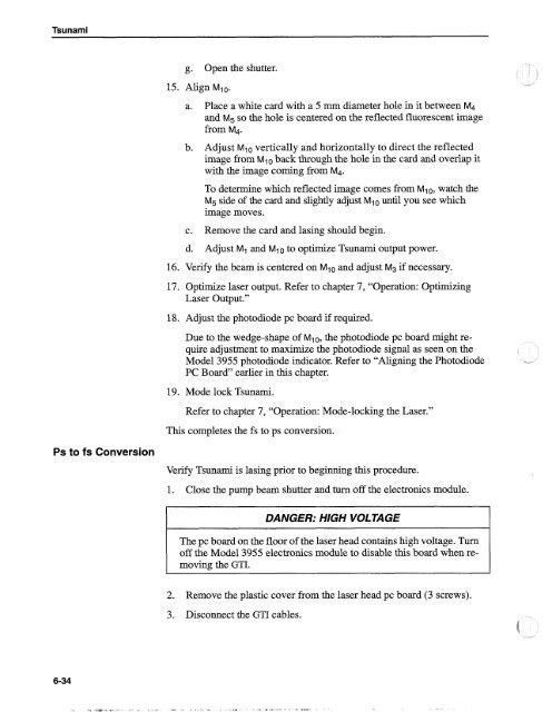
g. Open the shutter.<br />
15. Align MI0.<br />
a. Place a white card with a 5 mrn diameter hole in it between M4<br />
and M5 SO the hole is centered on the reflected fluorescent image<br />
from M4.<br />
b. Adjust M10 vertically and horizontally to direct the reflected<br />
image from Mlo back through the hole in the card and overlap it<br />
with the image coming from M4.<br />
To determine which reflected image comes from MlO, watch the<br />
M5 side of the card and slightly adjust MI0 until you see which<br />
image moves.<br />
c. Remove the card and lasing should begin.<br />
d. Adjust MI and Mlo to optimize <strong>Tsunami</strong> output power.<br />
16. Verify the beam is centered on Mlo and adjust M3 if necessary.<br />
17. Optimize laser output. Refer to chapter 7, "Operation: Optimizing<br />
<strong>Laser</strong> Output."<br />
18. Adjust the photodiode pc board if required.<br />
Due to the wedge-shape of Mlo, the photodiode pc board might require<br />
adjustment to maximize the photodiode signal as seen on the<br />
Model 3955 photodiode indicator. Refer to "Aligning the Photodiode -<br />
PC Board" earlier in this chapter.<br />
19. Mode lock <strong>Tsunami</strong>.<br />
Refer to chapter 7, "Operation: Mode-locking the <strong>Laser</strong>."<br />
This completes the fs to ps conversion.<br />
Ps to fs Conversion<br />
Verify <strong>Tsunami</strong> is lasing prior to beginning this procedure.<br />
1. Close the pump beam shutter and turn off the electronics module.<br />
DANGER: HIGH VOLTAGE<br />
The pc board on the floor of the laser head contains high voltage. Turn<br />
off the Model 3955 electronics module to disable this board when removing<br />
the GTI.<br />
2. Remove the plastic cover from the laser head pc board (3 screws).<br />
3. Disconnect the GTI cables.


