Tsunami - Beckman Institute Laser Resource Center
Tsunami - Beckman Institute Laser Resource Center
Tsunami - Beckman Institute Laser Resource Center
Create successful ePaper yourself
Turn your PDF publications into a flip-book with our unique Google optimized e-Paper software.
Controls, Indicators and Connections<br />
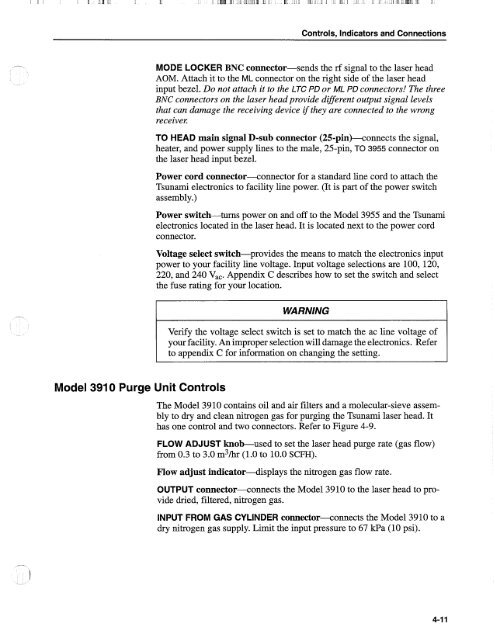
MODE LOCKER BNC connector-sends the rf signal to the laser head<br />
AOM. Attach it to the ML connector on the right side of the laser head<br />
input bezel. Do not attach it to the LTC PD or ML PD connectors! The three<br />
BNC connectors on the laser head provide difSerent output signal levels<br />
that can damage the receiving device if they are connected to the wrong<br />
receivel:<br />
TO HEAD main signal D-sub connector (25-pin)-connects the signal,<br />
heater, and power supply lines to the male, 25-pin, TO 3955 connector on<br />
the laser head input bezel.<br />
Power cord connector-connector for a standard line cord to attach the<br />
<strong>Tsunami</strong> electronics to facility line power. (It is part of the power switch<br />
assembly.)<br />
Power switch-turns power on and off to the Model 3955 and the <strong>Tsunami</strong><br />
electronics located in the laser head. It is located next to the power cord<br />
connector.<br />
Voltage select switch-provides the means to match the electronics input<br />
power to your facility line voltage. Input voltage selections are 100, 120,<br />
220, and 240 V,,. Appendix C describes how to set the switch and select<br />
the fuse rating for your location.<br />
WARNING<br />
Verify the voltage select switch is set to match the ac line voltage of<br />
your facility. An improper selection will damage the electronics. Refer<br />
to appendix C for information on changing the setting.<br />
Model 3910 Purge Unit Controls<br />
The Model 3910 contains oil and air filters and a molecular-sieve assembly<br />
to dry and clean nitrogen gas for purging the <strong>Tsunami</strong> laser head. It<br />
has one control and two connectors. Refer to Figure 4-9.<br />
FLOW ADJUST knob-used to set the laser head purge rate (gas flow)<br />
from 0.3 to 3.0 m3/hr (1.0 to 10.0 SCFH).<br />
Flow adjust indicator--displays the nitrogen gas flow rate.<br />
OUTPUT connector--connects the Model 3910 to the laser head to provide<br />
dried, filtered, nitrogen gas.<br />
INPUT FROM GAS CYLINDER connector+onnects the Model 3910 to a<br />
dry nitrogen gas supply. Limit the input pressure to 67 kPa (10 psi).


