

Tsunami - Beckman Institute Laser Resource Center
Tsunami - Beckman Institute Laser Resource Center
Tsunami - Beckman Institute Laser Resource Center

Create successful ePaper yourself
Turn your PDF publications into a flip-book with our unique Google optimized e-Paper software.
Alignment<br />
b. Remove the plastic cover from the laser head pc board (3). and<br />
disconnect the gray GTI heater cable from connector J2<br />
(Figure 5-5).<br />
c. Disconnect the black coaxial control cable from the GTI by pulling<br />
it straight off.<br />
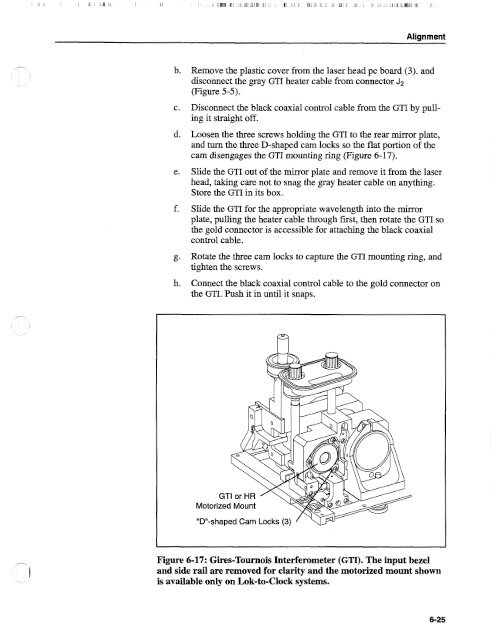
d. Loosen the three screws holding the GTI to the rear mirror plate,<br />
and turn the three D-shaped cam locks so the flat portion of the<br />
cam disengages the GTI mounting ring (Figure 6-17).<br />
e. Slide the GTI out of the mirror plate and remove it from the laser<br />
head, taking care not to snag the gray heater cable on anything.<br />
Store the GTI in its box.<br />
f. Slide the GTI for the appropriate wavelength into the mirror<br />
plate, pulling the heater cable through first, then rotate the GTI so<br />
the gold connector is accessible for attaching the black coaxial<br />
control cable.<br />
g. Rotate the three cam locks to capture the GTI mounting ring, and<br />
tighten the screws.<br />
h. Connect the black coaxial control cable to the gold connector on<br />
the GTI. Push it in until it snaps.<br />
Figure 6-17: Gires-Tournois Interferometer (GTI). The input bezel<br />
and side rail are removed for clarity and the motorized mount shown<br />
is available only on Lok-to-Clock systems.


