

Tsunami - Beckman Institute Laser Resource Center
Tsunami - Beckman Institute Laser Resource Center
Tsunami - Beckman Institute Laser Resource Center

You also want an ePaper? Increase the reach of your titles
YUMPU automatically turns print PDFs into web optimized ePapers that Google loves.
I I1 ! I : I I I ill 8 I !Il! I1I l,ll ;Ill1 !Ill Bl 11 a I Ill , I1 1 Ill; ,I1 t I ,I, ik, I 11 I I I! I<br />
Lok-to-Clock Electronics<br />
Functional Overview<br />
The optional Model 3930 Lok-to-Clock (LTC) electronics module provides<br />
phase-locked loop (PLL) stabilization of output pulses and allows<br />
you to precisely synchronize those output pulses to either the internal 80<br />
MHz reference source or to an external one, such as an rf synthesizer or<br />
another mode-locked laser. The LTC system is capable of reducing timing<br />
jitter to < 3 ps rms (100 Hz to 10 kHz).<br />
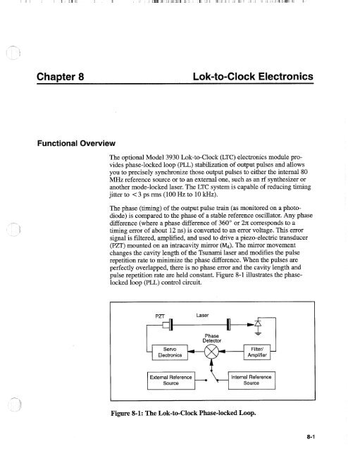
The phase (timing) of the output pulse train (as monitored on a photodiode)<br />
is compared to the phase of a stable reference oscillator. Any phase<br />
difference (where a phase difference of 360" or 2n corresponds to a<br />
timing error of about 12 ns) is converted to an error voltage. This error<br />
signal is filtered, amplified, and used to drive a piezo-electric transducer<br />
(PZT) mounted on an intracavity mirror (M4). The mirror movement<br />
changes the cavity length of the <strong>Tsunami</strong> laser and modifies the pulse<br />
repetition rate to minimize the phase difference. When the pulses are<br />
perfectly overlapped, there is no phase error and the cavity length and<br />
pulse repetition rate are held constant. Figure 8-1 illustrates the phaselocked<br />
loop (PLL) control circuit.<br />
PZT<br />
<strong>Laser</strong><br />
I t<br />
-<br />
Phase<br />
Detector<br />
- Servo<br />
Filter1 -<br />
Electronics Amplifier<br />
Source<br />
Internal Reference<br />
Source<br />
Figure 8-1: The Lok-to-Clock Phase-locked Loop.<br />
8-1


