

Tsunami - Beckman Institute Laser Resource Center
Tsunami - Beckman Institute Laser Resource Center
Tsunami - Beckman Institute Laser Resource Center

You also want an ePaper? Increase the reach of your titles
YUMPU automatically turns print PDFs into web optimized ePapers that Google loves.
Alignment<br />
Changing the Prism Setting<br />
To determine which reflected image comes from Mlo, watch the<br />
output side of the card and slightly adjust MI0 until you see which<br />
image moves.<br />
c. Remove the card.<br />
14. Remove the card placed in front of the output window and place a<br />
power meter in the beam path.<br />
If you own a Model 3950 ps-only laser without prism mounts, skip to step<br />
20 in the next section. For fs operation, continue starting here.<br />
Due to the difference in the index of refraction for the different wavelengths,<br />
the intracavity beam will be either too high or too low on prisms<br />
Pr2 and Pr3 when you change wavelength ranges and it is necessary to<br />
adjust the vertical controls for mirrors M6, M7, M8, and M9 to reposition the<br />
beam properly on the prisms. Lasing should resume when the last vertical<br />
adjustment is made.<br />
Once the beam is properly positioned on the prisms, the prisms themselves<br />
must be adjusted to provide the right amount of GVD compensation for the<br />
wavelength range selected. It is the amount of prism glass exposed to the<br />
laser beam that determines the amount of GVD compensation. In general,<br />
the blue range requires the most prism glass to minimize the pulse width.<br />
Thus, when converting from blue or standard to long or x-long, or vice<br />
versa, Prl and Pr4 must be adjusted according to Table 6-4 and Figure 6-18<br />
to provide the proper amount of glass.<br />
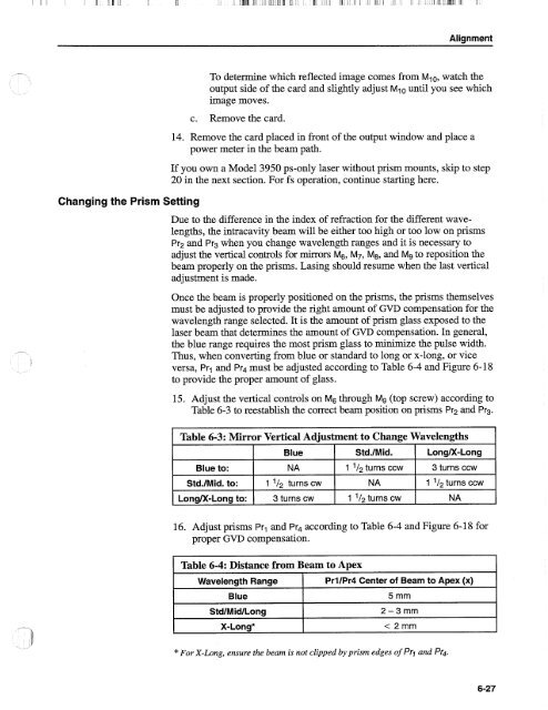
15. Adjust the vertical controls on M6 through M9 (top screw) according to<br />
Table 6-3 to reestablish the correct beam position on prisms Pr2 and Pr3.<br />
Table 6-3: Mirror Vertical Adjustment to Change Wavelengths<br />
Blue to:<br />
Std./Mid. to:<br />
Blue<br />
NA<br />
1 turns cw<br />
Std.1Mid.<br />
1 turns ccw<br />
NA<br />
1 turns cw<br />
LongM-Long<br />
3 turns ccw<br />
1 turns ccw<br />
LongM-Long to:<br />
3 turns cw<br />
NA<br />
16. Adjust prisms Prl and Pr4 according to Table 6-4 and Figure 6-18 for<br />
proper GVD compensation.<br />
Table 6-4: Distance from Beam to Apex<br />
Wavelength Range<br />
Blue<br />
StdIMidlLong<br />
X-Long*<br />
PrllPr4 <strong>Center</strong> of Beam to Apex (x)<br />
5 mm<br />
2-3mm<br />
< 2mm<br />
*For X-Long, ensure the beam is not clipped by prism edges of Pr, and Pr4.


