Tsunami - Beckman Institute Laser Resource Center
Tsunami - Beckman Institute Laser Resource Center
Tsunami - Beckman Institute Laser Resource Center
You also want an ePaper? Increase the reach of your titles
YUMPU automatically turns print PDFs into web optimized ePapers that Google loves.
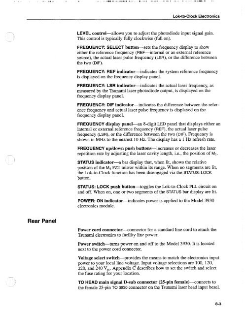
Lok-to-Clock Electronics<br />
LEVEL control-allows you to adjust the photodiode input signal gain.<br />
This control is typically fully clockwise (full on).<br />
FREQUENCY: SELECT button-sets the frequency display to show<br />
either the reference frequency (REF-internal or an external reference<br />
source), the actual laser pulse frequency (LSR), or the difference between<br />
the two (DIF).<br />
FREQUENCY: REF indicator-indicates the system reference frequency<br />
is displayed on the frequency display panel.<br />
FREQUENCY: LSR indicator-indicates the actual laser frequency, as<br />
measured by the <strong>Tsunami</strong> laser photodiode output, is displayed on the<br />
frequency display panel.<br />
FREQUENCY: DIF indicator-indicates the difference between the reference<br />
frequency and actual laser pulse frequency is displayed on the<br />
frequency display panel.<br />
FREQUENCY display panel-an 8-digit LED panel that displays either an<br />
internal or external reference frequency (REF), the actual laser pulse<br />
frequency (LSR), or the difference between the two (DIF). Frequency is<br />
shown in MHz to the nearest 10 Hz. The display has a 1 Hz refresh rate.<br />
FREQUENCY up/down push buttons-increases or decreases the laser<br />
repetition rate by adjusting the laser cavity length, i.e., the position of MI.<br />
STATUS indicator-a bar display that, when lit, shows the relative<br />
position of the M4 PZT mirror within its range. When no segments are lit,<br />
the Lok-to-Clock function has been disengaged via the STATUS: LOCK<br />
button.<br />
STATUS: LOCK push button-toggles the Lok-to-Clock PLL circuit on<br />
and off. When on, one or two segments of the STATUS bar display are lit.<br />
POWER: ON indicator-indicates power is applied to the Model 3930<br />
electronics module.<br />
Rear Panel<br />
Power cord connector--connector for a standard line cord to attach the<br />
<strong>Tsunami</strong> electronics to facility line power.<br />
Power switch-turns power on and off to the Model 3930. It is located<br />
next to the power cord connector.<br />
Voltage select switch-provides the means to match the electronics input<br />
power to your local line voltage. Input voltage selections are 100, 120,<br />
220, and 240 V,,. Appendix C describes how to set the switch and select<br />
the fuse rating for your location.<br />
TO HEAD main signal D-sub connector (25-pin female)--connects to<br />
the female 25-pin TO 3930 connector on the <strong>Tsunami</strong> laser head input bezel.


