Tsunami - Beckman Institute Laser Resource Center
Tsunami - Beckman Institute Laser Resource Center
Tsunami - Beckman Institute Laser Resource Center
Create successful ePaper yourself
Turn your PDF publications into a flip-book with our unique Google optimized e-Paper software.
<strong>Tsunami</strong><br />
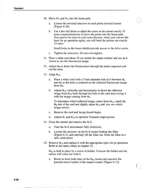
10. Move Prl and Pr4 into the beam path.<br />
a. Loosen the dovetail setscrew on each prism dovetail mount<br />
(Figure 6- 16).<br />
b. Use a hex ball driver to adjust the screw on the mount exactly 10<br />
turns counterclockwise to move the prism into the beam path.<br />
You need to be exact in your turns because, when you convert the<br />
laser for ps operation again, you will back the prisms out exactly<br />
10 turns.<br />
Small holes in the beam shields provide access to the drive screw.<br />
c. Tighten the setscrews. Do not over-tighten.<br />
11. Place a white card about 10 cm outside the output window and use an ir<br />
viewer to see the fluorescent image.<br />
12. Adjust M5 to direct the fluorescence through the prism sequence and<br />
out the laser.<br />
13. Align MlO.<br />
a. Place a white card with a 5 mm diameter hole in it between M4<br />
and M5 SO the hole is centered on the reflected fluorescent image<br />
from M4.<br />
b. Adjust MI0 vertically and horizontally to direct the reflected<br />
image from Mi 0 back through the hole in the card and overlap it<br />
with the image coming from M4.<br />
To determine which reflected image comes from Ml0, watch the<br />
M5 side of the card and slightly adjust Ml0 until you see which<br />
image moves.<br />
c. Remove the card and lasing should begin.<br />
d. Adjust M1 and Mlo to optimize <strong>Tsunami</strong> output power.<br />
14. Close the shutter and remove the bi-fi.<br />
a. Turn the bi-fi micrometer fully clockwise.<br />
b. Loosen the setscrew on the bi-fi mount holding the filter<br />
(Figure 6-3), and carefully lift the filter out. Store the filter in a<br />
safe, clean place.<br />
15. Remove Mlo and replace it with the appropriate optic for ps operation.<br />
Refer to the optics tables in chapter 10.<br />
Mlo is held in place by a screw-in holder. Unscrew the holder and the<br />
mirror will come out with it.<br />
a. Reach in from both sides of the Ml0 mount and unscrew the<br />
knurled mirror holder of the output coupler (Figure 6-12).


