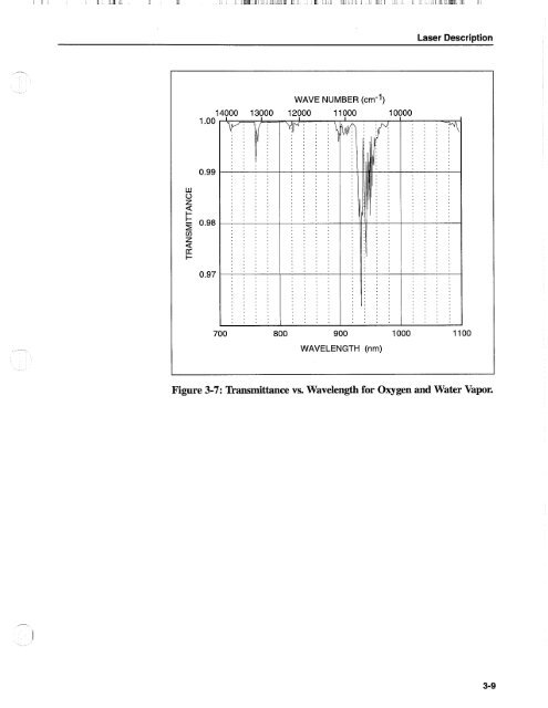
<strong>Tsunami</strong> Pulse Width Selection Purging the <strong>Tsunami</strong> The pulse width tuning characteristics of the Ti:sapphire laser are influenced by two factors: those inherent in the Ti:sapphire material itself and those from cavity parameters. While we cannot readily modify the Ti:sapphire material to change pulse width, we can modify the net group velocity dispersion (GVD). The optical components in the laser cavity introduce positive GVD and cause pulse spreading. Further pulse spreading is caused by self-phase modulation (SPM) in the Ti:sapphire rod, which results from the interaction of the short optical pulse with the nonlinear refractive index. In order to obtain stable, short output pulses, these effects must be compensated with negative GVD. fs systems. Prism pairs are used to produce a net negative intracavity GVD in the fs system. This allows the system to produce < 80 fs near transformlimited pulses over most of the <strong>Tsunami</strong> wavelength regime. ps systems. In the ps configuration, a GTI is used to provide negative GVD in a patented mode locking design. This device is similar to a Fabry- Perot interferometer, except the first mirror is a partial reflector instead of a high reflector. It has the advantage of being highly reflective over a broad spectral range, yet provides a frequency-dependent optical phase shift. It also provides adjustable negative GVD when the distance between the mirrors is varied. The GTI produces a fairly large negative GVD that is linear over a narrow bandwidth. It, therefore, must be readjusted whenever a new wavelength is selected. The GTI POSITION control adjusts this spacing and allows you to obtain < 2 ps near transform-limited output pulses - over the entire <strong>Tsunami</strong> wavelength regime. For a full review of GVD and compensation, please refer to appendix A, "Mode Locking: Group Velocity Dispersion." The <strong>Tsunami</strong> head is sealed so it can be purged. The Model 3910 regulatorlfilter purge unit is provided for filtering and drying bottled nitrogen gas. Purging the laser cavity with this gas not only eliminates the typical problems associated with dust and contamination, but also prevents tuning discontinuities caused by oxygen and water vapor. Reduction of the latter is important for operation in the long wavelengths (Figure 3-7). -
I IIIIIN III I I 1 I 11111 i~ I I I u 11 I I I I i I I I r I I II 11 Plmi 111 I <strong>Laser</strong> Descri~tion WAVE NUMBER (cm-1) 14000 13000 12000 1 1000 I0000 1 .oo 0.99 . . . . , , , . s , . , . , , , , s , s . . , . . . , , , , , , , , , , LU , , , . . , . . . 0 , , , , , , , , z . . . , , , , , . . . a , . , , , , , , , , , , , . , . , , , . , , , . . , . . , , , . . , , , , . . . , , , , , , . . , , , , , , . . . s , . . . . . . , 0.98 : : , . . . , , , , , , , , , , , 5 . . . . . . . . . , , , , , , , , s . . , , , . Z s . . , . . , . . , . , , , , a , , , . . . , , . . , . , LT , . , , . , , , . , I- . . . , , , . , , , , , , . , s , . . . . , . . . . . , , , , . , , , , s . . , , , . , . . . . , , , , . . . . , , , . , , , , , . . , . , , . , ., . , , , . s . . . . , , . , , , , . , , , . . , , , . . . . . , . . , , . . , . , , , , , . . . . . 700 800 900 1000 1100 WAVELENGTH (nm) Figure 3-7: lhnsrnittance vs. Wavelength for Oxygen and Water Vapor.
- Page 1: Tsunami Mode-locked Ti: sapphire La
- Page 5 and 6: Table of Contents ... Preface .....
- Page 7 and 8: Table of Contents . Chapter 6: Alig
- Page 9 and 10: Table of Contents Chapter 10: Optio
- Page 11 and 12: Table of Contents Figure 4-7: Typic
- Page 13 and 14: Table of Contents Figure A-6: The f
- Page 15: Warning Conventions The following w
- Page 19: List of Abbreviations Used in this
- Page 22 and 23: Tsunami Figure 1-1: The Tsunami Las
- Page 25 and 26: Chapter 2 Laser Safety DANGER The T
- Page 27 and 28: Laser Safety CA UTlON Use of contro
- Page 29 and 30: 1 1 1 Il I 11 I I 1 El l11111II~Ill
- Page 31 and 32: Chapter 3 Laser Description General
- Page 33 and 34: Laser Description growth techniques
- Page 35 and 36: Laser Description - AOM OC n Fast P
- Page 37: Laser Description 2.4 - 2.2 - 2.0 -
- Page 41 and 42: I II li I I I i 1 il I 1 11 I 1 1 1
- Page 43: I Laser Description . Outline Dimen
- Page 46 and 47: Tsunami Input Bezel Connections The
- Page 48 and 49: Tsunami Opto-Mechanical Controls Al
- Page 50 and 51: Tsunami Blue Knob: Vertical Adjust
- Page 52 and 53: ~lpl~ f \ Tsunami Opto-Mechanical C
- Page 54 and 55: Tsunami Figure 4-7: 'Qpical MONITOR
- Page 56 and 57: Tsunami r @ Spectra-Physics - - 4 2
- Page 58 and 59: Tsunami Laser Installation Installi
- Page 60 and 61: Tsunami Setting up the Routing Mirr
- Page 62 and 63: Tsunami Aligning the Tsunami Laser
- Page 64 and 65: Tsunami A -----------. PHOTODIODE O
- Page 66 and 67: Tsunami Removing the Purge Line fro
- Page 68 and 69: Tsunami Motorized Mount "Dm-shaped
- Page 70 and 71: Tsunami I I J3 3930 - - - #,-,I --J
- Page 72 and 73: Tsunami CA UTION DO NOT remove or a
- Page 74 and 75: Tsunami Refer to the tables at the
- Page 76 and 77: Tsunami b. Move the stage by hand a
- Page 78 and 79: Tsunami There will be one or two re
- Page 80 and 81: Tsunami Figure 6-9: The Slit Contro
- Page 82 and 83: Tsunami b. Place a white card with
- Page 84 and 85: Tsunami Aligning the Photodiode PC
- Page 86 and 87: Tsunami To measure pulses, use a Sp
- Page 88 and 89:
Tsunami pulses, adjust the coarse c
- Page 90 and 91:
Tsunami Selecting, Installing, and
- Page 92 and 93:
Tsunami Unless you are certain the
- Page 94 and 95:
Tsunami Prism Translation Adjust Fi
- Page 96 and 97:
Tsunami i. Route the GTI heater cab
- Page 98 and 99:
Tsunami Figure 6-18: Pr1/Pr4 prisms
- Page 100 and 101:
Tsunami Converting Between fs and p
- Page 102 and 103:
Tsunami b. Using an ir viewer, adju
- Page 104 and 105:
Tsunami g. Open the shutter. 15. Al
- Page 106 and 107:
Tsunami 10. Move Prl and Pr4 into t
- Page 108 and 109:
Tsunami 21. Mode lock Tsunami. Refe
- Page 110 and 111:
I " n 3 1 ' ! ' I . I 8 8 8 " t 8 0
- Page 112 and 113:
Tsunami recommend using 99.999% pur
- Page 114 and 115:
Tsunami Mode Locking the Laser 6. W
- Page 116 and 117:
Tsunami - - - 710 nrn - - 790 nrn -
- Page 118 and 119:
4 Tsunami Beam % 2 mm (0.08 in.) Pr
- Page 120 and 121:
Tsunami Table 7-1: Bi-fi Selection
- Page 123 and 124:
I I1 ! I : I I I ill 8 I !Il! I1I l
- Page 125 and 126:
Lok-to-Clock Electronics LEVEL cont
- Page 127 and 128:
Lok-to-Clock Electronics AOM M5f-4
- Page 129 and 130:
Lok-to-Clock Electronics Installing
- Page 131 and 132:
I I1 I i l l I iil 111 ,111 Ill ,il
- Page 133 and 134:
P Lok-to-Clock Electronics Model 20
- Page 135 and 136:
I 1 1 I 1~~~ 11 I 1 1 1 1 .III :ill
- Page 137 and 138:
Lok-to-Clock Electronics Figure 8-9
- Page 139:
I I1 I l I 1 bll Lok-to-Clock Elect
- Page 142 and 143:
Tsunami "Clean" is a relative descr
- Page 144 and 145:
Tsunami Figure 9-1: Drop and Drag M
- Page 146 and 147:
Tsunami With the exception of pump
- Page 148 and 149:
Tsunami On rare occasions, the lowe
- Page 150 and 151:
Tsunami 8. Open the pump laser shut
- Page 152 and 153:
Tsunami 7. Remove the screws (4) ho
- Page 154 and 155:
Tsunami DryJClean Flow Adjust Nitro
- Page 156 and 157:
Tsunami diode such as the Model 393
- Page 158 and 159:
€968-PEP0 ES68-PEP0 PS68-PEP0 ES6
- Page 160 and 161:
Tsunami Check marks indicate which
- Page 162 and 163:
Tsunami Table 10-11: GTI and Bi-Pi
- Page 164 and 165:
Tsunami Generic Troubleshooting (No
- Page 166 and 167:
Tsunami Symptom: Laser will not mod
- Page 168 and 169:
Tsunami Symptom: Unable to mode loc
- Page 170 and 171:
Tsunami Symptom: Unable to mode loc
- Page 172 and 173:
Tsunami Symptom: Cannot see individ
- Page 174 and 175:
Tsunami Symptom: PZT oscillates whe
- Page 177 and 178:
I I ill ; I l l I I lll.l1 I I I *
- Page 179 and 180:
I I 111 il I iil i lllill ll I I ll
- Page 181 and 182:
I I il : I I I 1 I Appendix A Mode
- Page 183 and 184:
Mode Locking is chosen to be the sa
- Page 185 and 186:
I I 0 I I 1 I )I Ulllllll ill I Mod
- Page 187 and 188:
Mode Locking SPM will, thus, broade
- Page 189 and 190:
Mode Locking The net intracavity GV
- Page 191 and 192:
Appendix B Pulse Width Measurement
- Page 193 and 194:
I I 0 I I 1 1 LI I lillll Ill I!,ll
- Page 195 and 196:
Pulse Width Measurement -% GVD Comp
- Page 197 and 198:
I I I I I I I I ti 911 I1 I Pulse W
- Page 199 and 200:
I I I I I I B I IL 1 1 i 1111 I L I
- Page 201 and 202:
I I 0 I I 1 1 L I I Pulse Width Mea
- Page 203 and 204:
Appendix C Setting the Line Voltage
- Page 205 and 206:
Appendix D Material Safetv Data She
- Page 207 and 208:
Material Safety Data Sheets MATERIA
- Page 209 and 210:
I I I 1 r $1 I Bill II I I I I Ill
- Page 211 and 212:
Material Safety Data Sheets MATERIA