

Tsunami - Beckman Institute Laser Resource Center
Tsunami - Beckman Institute Laser Resource Center
Tsunami - Beckman Institute Laser Resource Center

You also want an ePaper? Increase the reach of your titles
YUMPU automatically turns print PDFs into web optimized ePapers that Google loves.
<strong>Tsunami</strong><br />
I<br />
I<br />
J3<br />
3930<br />
- - -<br />
#,-,I<br />
--J<br />
I<br />
I I - - -<br />
.------a<br />
Top View<br />
I t - \ l<br />
I\ 11<br />
I-'= -I<br />
J2<br />
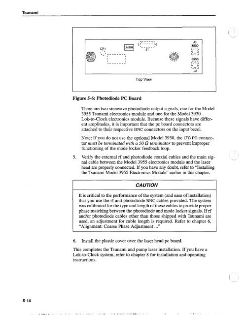
Figure 5-6: Photodiode PC Board<br />
There are two sinewave photodiode output signals, one for the Model<br />
3955 <strong>Tsunami</strong> electronics module and one for the Model 3930<br />
Lok-to-Clock electronics module. Because these signals have different<br />
amplitudes, it is important that the pc board connectors are<br />
attached to their respective BNC connectors on the input bezel.<br />
Note: If you do not use the optional Model 3930, the LTC PD connector<br />
must be terminated with a 50 SZ terminator to prevent improper<br />
functioning of the mode locker feedback loop.<br />
5. Venfy the external rf and photodiode coaxial cables and the main signal<br />
cable between the Model 3955 electronics module and the laser<br />
head are properly connected. If you have any doubt, refer to "Installing<br />
the <strong>Tsunami</strong> Model 3955 Electronics Module" earlier in this chapter.<br />
CAUTION<br />
It is critical to the performance of the system (and ease of installation)<br />
that you use the rf and photodiode BNC cables provided. The system<br />
was calibrated for the type and length of these cables to provide proper<br />
phase matching between the photodiode and mode locker signals. If rf<br />
andfor photodiode cables other than those shipped with <strong>Tsunami</strong> are<br />
used, an adjustment for cable length is required. Refer to chapter 6,<br />
"Alignment: Coarse Phase Adjustment ..."<br />
6. Install the plastic cover over the laser head pc board.<br />
This completes the <strong>Tsunami</strong> and pump laser installation. If you have a<br />
Lok-to-Clock system, refer to chapter 8 for installation and operating<br />
instructions.


