Tsunami - Beckman Institute Laser Resource Center
Tsunami - Beckman Institute Laser Resource Center
Tsunami - Beckman Institute Laser Resource Center
You also want an ePaper? Increase the reach of your titles
YUMPU automatically turns print PDFs into web optimized ePapers that Google loves.
<strong>Tsunami</strong><br />
pulses, adjust the coarse control located inside the Model 3955. Refer<br />
to "Coarse Phase Adjustment ..." at the end of this chapter for instruc- --<br />
tions on locating and changing the setting of the coarse control.<br />
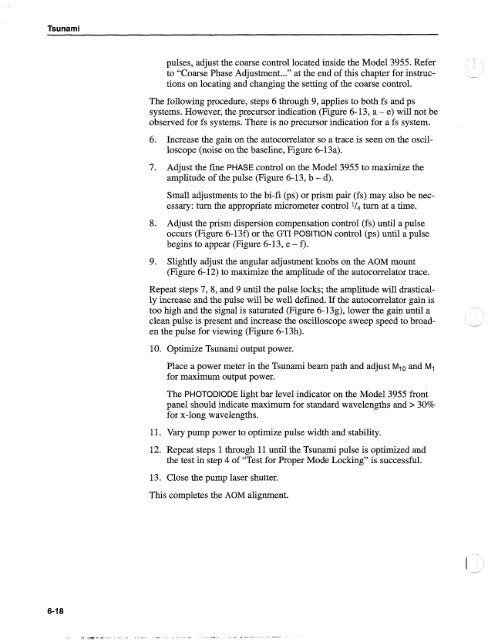
The following procedure, steps 6 through 9, applies to both fs and ps<br />
systems. However, the precursor indication (Figure 6-13, a - e) will not be<br />
observed for fs systems. There is no precursor indication for a fs system.<br />
6. Increase the gain on the autocorrelator so a trace is seen on the oscilloscope<br />
(noise on the baseline, Figure 6- 13a).<br />
7. Adjust the fine PHASE control on the Model 3955 to maximize the<br />
amplitude of the pulse (Figure 6-13, b - d).<br />
Small adjustments to the bi-fi @s) or prism pair (fs) may also be necessary:<br />
turn the appropriate micrometer control turn at a time.<br />
8. Adjust the prism dispersion compensation control (fs) until a pulse<br />
occurs (Figure 6-130 or the GTI POSITION control (ps) until a pulse<br />
begins to appear (Figure 6- 13, e - f).<br />
9. Slightly adjust the angular adjustment knobs on the AOM mount<br />
(Figure 6-12) to maximize the amplitude of the autocorrelator trace.<br />
Repeat steps 7,8, and 9 until the pulse locks; the amplitude will drastically<br />
increase and the pulse will be well defined. If the autocorrelator gain is<br />
too high and the signal is saturated (Figure 6-13g), lower the gain until a<br />
clean pulse is present and increase the oscilloscope sweep speed to broaden<br />
the pulse for viewing (Figure 6-13h).<br />
10. Optimize <strong>Tsunami</strong> output power.<br />
Place a power meter in the <strong>Tsunami</strong> beam path and adjust Mlo and M1<br />
for maximum output power.<br />
The PHOTODIODE light bar level indicator on the Model 3955 front<br />
panel should indicate maximum for standard wavelengths and > 30%<br />
for x-long wavelengths.<br />
11. Vary pump power to optimize pulse width and stability.<br />
12. Repeat steps 1 through 11 until the <strong>Tsunami</strong> pulse is optimized and<br />
the test in step 4 of "Test for Proper Mode Locking" is successful.<br />
13. Close the pump laser shutter.<br />
This completes the AOM alignment.


