

Tsunami - Beckman Institute Laser Resource Center
Tsunami - Beckman Institute Laser Resource Center
Tsunami - Beckman Institute Laser Resource Center

You also want an ePaper? Increase the reach of your titles
YUMPU automatically turns print PDFs into web optimized ePapers that Google loves.
<strong>Tsunami</strong><br />
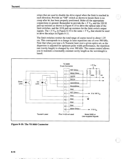
relays that are used to disable the drive signal when the limit is reached in<br />
each direction. Provide an "Off" switch as shown to insure there is no -<br />
creep after M1 has been properly positioned. Make all the appropriate<br />
connections to ground. Remember to provide the + 5 Vdc and the 220 G<br />
pull-up resistors as shown in Figure 8-10 to drive the optical side of the<br />
limit switches, and the 10 K pull-up resistors for the limit switch output<br />
signals. The + 5 Vdc in Figure 8-10 is the same + 5 Vdc that should be used<br />
to drive the relays in Figure 8- 11.<br />
The limit switches restrict the total range of coarse travel to about 1.25<br />
cm. This corresponds to a change in laser repetition rate of over 500 kHz.<br />
Note that when you tune a fs <strong>Tsunami</strong> laser over a given optics set, as the<br />
dispersion is adjusted for optimum pulse width performance, the repetition<br />
rate (cavity length) is changed by over 300 H z. The coarse control allows<br />
you to maintain a reasonably constant cavity length as the wavelength is<br />
tuned.<br />
TO 3930<br />
D-sub Connector<br />
+ 5 Vdc<br />
---------I<br />
1)<br />
3)<br />
4)<br />
><br />
,><br />
8><br />
PZT Drive -<br />
Motor Drive -<br />
UpLim<br />
DnLim<br />
UpLirnDrive<br />
DnLimDrive<br />
Gnd<br />
PZT Drive +<br />
Gnd<br />
4l<br />
220Q<br />
-<br />
* 0 to 100Vdc<br />
10)<br />
11)<br />
12)<br />
13><br />
Grid 4)<br />
Grid ,I<br />
Gnd<br />
Motor Drive +<br />
* f 10 Vdc<br />
<strong>Tsunami</strong> <strong>Laser</strong> Pins 14-25 not used Model 3930 or<br />
User-supplied Signals<br />
Figure 8-10: The TO 3930 Connector


