

Tsunami - Beckman Institute Laser Resource Center
Tsunami - Beckman Institute Laser Resource Center
Tsunami - Beckman Institute Laser Resource Center

You also want an ePaper? Increase the reach of your titles
YUMPU automatically turns print PDFs into web optimized ePapers that Google loves.
<strong>Tsunami</strong><br />
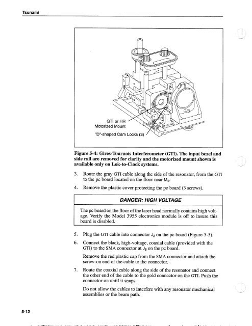
Motorized Mount<br />
"Dm-shaped Cam Locks (3)<br />
Figure 5-4: Gires-Tournois Interferometer (GTI). The input bezel and<br />
side rail are removed for clarity and the motorized mount shown is<br />
available only on Lok-to-Clock systems. -*<br />
3. Route the gray GTI cable along the side of the resonator, from the GTI<br />
to the pc board located on the floor near M4.<br />
4. Remove the plastic cover protecting the pc board (3 screws).<br />
DANGER: HIGH VOLTAGE<br />
The pc board on the floor of the laser head normally contains high voltage.<br />
Verify the Model 3955 electronics module is off to insure this<br />
board is disabled.<br />
5. Plug the GTI cable into connector J2 on the pc board (Figure 5-5).<br />
6. Connect the black, high-voltage, coaxial cable (provided with the<br />
GTI) to the SMA connector at J6 on the pc board.<br />
Remove the red plastic cap from the SMA connector and attach the<br />
screw-on end of the cable to the connector.<br />
7. Route the coaxial cable along the side of the resonator and connect<br />
the other end of the cable to the gold connector on the GTI. Push the<br />
connector on until it snaps.<br />
Do not allow the cables to interfere with any resonator mechanical<br />
assemblies or the beam path.<br />
I<br />
--


