Tsunami - Beckman Institute Laser Resource Center
Tsunami - Beckman Institute Laser Resource Center
Tsunami - Beckman Institute Laser Resource Center
Create successful ePaper yourself
Turn your PDF publications into a flip-book with our unique Google optimized e-Paper software.
Maintenance<br />
- -<br />
I<br />
Replacing Filters in the Model 3910 Purge Unit<br />
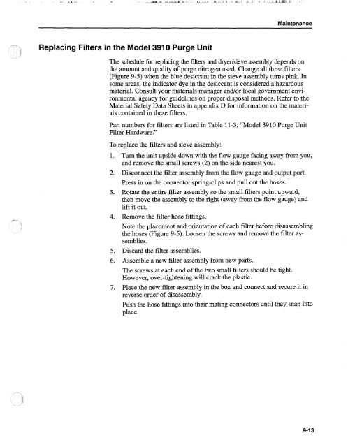
The schedule for replacing the filters and dryerhieve assembly depends on<br />
the amount and quality of purge nitrogen used. Change all three filters<br />
(Figure 9-5) when the blue desiccant in the sieve assembly turns pink. In<br />
some areas, the indicator dye in the desiccant is considered a hazardous<br />
material. Consult your materials manager and/or local government environmental<br />
agency for guidelines on proper disposal methods. Refer to the<br />
Material Safety Data.Sheets in appendix D for information on the materials<br />
contained in these filters.<br />
Part numbers for filters are listed in Table 11-3, "Model 3910 Purge Unit<br />
Filter Hardware."<br />
To replace the filters and sieve assembly:<br />
1. Turn the unit upside down with the flow gauge facing away from you,<br />
and remove the small screws (2) on the side nearest you.<br />
2. Disconnect the filter assembly from the flow gauge and output port.<br />
Press in on the connector spring-clips and pull out the hoses.<br />
3. Rotate the entire filter assembly so the small filters point upward,<br />
then move the assembly to the right (away from the flow gauge) and<br />
lift it out.<br />
4. Remove the filter hose fittings.<br />
Note the placement and orientation of each filter before disassembling<br />
the hoses (Figure 9-5). Loosen the screws and remove the filter assemblies.<br />
5. Discard the filter assemblies.<br />
6. Assemble a new filter assembly from new parts.<br />
The screws at each end of the two small filters should be tight.<br />
However, over-tightening will crack the plastic.<br />
7. Place the new filter assembly in the box and connect and secure it in<br />
reverse order of disassembly.<br />
Push the hose fittings into their mating connectors until they snap into<br />
place.


