

Tsunami - Beckman Institute Laser Resource Center
Tsunami - Beckman Institute Laser Resource Center
Tsunami - Beckman Institute Laser Resource Center

Create successful ePaper yourself
Turn your PDF publications into a flip-book with our unique Google optimized e-Paper software.
1 1 1 I 1111 1 81 I i 11110 II I 1 I Ll'il iiil ll iI I Ill I i ilU I I1 I 1<br />
-<br />
ti<br />
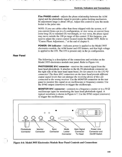
Figure 4-6: Model 3955 Electronics Module Rear Panel Controls and Connections<br />
Controls, Indicators and Connections<br />
Fine PHASE control-adjusts the phase relationship between the AOM<br />
signal and the photodiode signal to provide a pulse-locking mechanism.<br />
Its adjustment range is about 100 ps. Adjust this control to sync the mode<br />
locker to the pulse rate.<br />
NOTE: If you use cables other than those shipped with the system, or if<br />
you convert from a ps to a fs configuration, or vice versa, or convert from<br />
extra-long (X) to standard (S) wavelength, or vice versa, the phase signal<br />
may move outside the 100 ps range of this control. If this happens, you<br />
need to adjust the coarse control located inside the Model 3955. Refer to<br />
"Coarse Phase Adjustment ..." at the end of chapter 6.<br />
POWER: ON indicator-indicates power is applied to the Model 3955<br />
electronics module, the AOM heater and GTI heaters, and that high voltage<br />
is applied to the GTI. The GTI is present only in the ps configuration.<br />
Rear Panel<br />
The following is a description of the connections and switches on the<br />
Model 3955 electronics module rear panel. Refer to Figure 4-6.<br />
PHOTODIODE BNC connector-receives the control signal from the<br />
laser head photodiode. It attaches to the ML PD photodiode connector on<br />
the right side of the laser head input bezel. Do not attach it to the LTC PD<br />
connector! The three BNC connectors on the laser head provide different<br />
output signal levels that can damage the receiving device if they are<br />
connected to the wrong receiver. Use the MONITOR connector on the rear<br />
panel to monitor this signal on an oscilloscope or frequency counter. Use<br />
the SYNC output (sinewave) to trigger the oscilloscope.<br />
MONITOR BNC connector--connects to a frequency counter or to a 50 Q<br />
oscilloscope input for monitoring the laser head photodiode signal. A<br />
typical waveform is shown in Figure 4-7. Use the SYNC output (sinewave)<br />
to trigger the oscilloscope.<br />
f ><br />
a<br />
a<br />
240V 0<br />
<<br />
0 0 0<br />
[n]r>[x)<br />
\u \\ \\ \\<br />
0 ( , 10<br />
TO HEAD<br />
\\<br />
\\\ul<br />
Power Line<br />
Photodiode Monitor Sync Mode Main Signal<br />
Connector Connector Connector Locker Connector Connector and<br />
Connector To Head OnIOff Switch<br />
/


