

Tsunami - Beckman Institute Laser Resource Center
Tsunami - Beckman Institute Laser Resource Center
Tsunami - Beckman Institute Laser Resource Center

You also want an ePaper? Increase the reach of your titles
YUMPU automatically turns print PDFs into web optimized ePapers that Google loves.
<strong>Tsunami</strong><br />
L-<br />
0<br />
6<br />
a<br />
C<br />
3<br />
+<br />
n<br />
5<br />
I-<br />
- 2L<br />
c<br />
+<br />
I\<br />
Time -<br />
) \ I \ ) \<br />
n,<br />
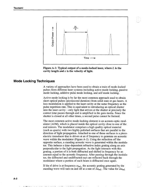
Figure A-1: Typical output of a mode-locked laser, where L is the<br />
cavity length and c is the velocity of light.<br />
Mode Locking Techniques<br />
A variety of approaches have been used to obtain a train of mode-locked<br />
pulses from different laser systems including active mode locking, passive<br />
mode locking, additive pulse mode locking, and self mode locking.<br />
Active mode locking is by far the most common approach used to obtain<br />
short optical pulses (picosecond duration) from solid state or gas lasers. A<br />
loss modulation is applied to the laser cavity at the same frequency as the<br />
pulse repetition rate. This is equivalent to introducing an optical shutter<br />
into the laser cavity--only light that arrives at the shutter at precisely the<br />
correct time passes through and is amplified in the gain media. Since the<br />
shutter is closed at all other times, a second pulse cannot be formed.<br />
The most common active mode-locking element is an acousto-optic modulator<br />
(AOM), which is placed inside the optical cavity close to one of the<br />
end mirrors. The modulator comprises a high quality optical material<br />
(such as quartz) with two highly polished surfaces that are parallel to the<br />
direction of light propagation. Attached to one of these surfaces is a piezoelectric<br />
transducer that is driven at an rf frequency to generate an acoustic<br />
wave within the modulator (Figure A-2). Using the reflection off the<br />
opposite surface, a standing acoustic wave is generated within the modulator.<br />
This induces a time-dependent refractive index grating along an axis<br />
perpendicular to the light propagation. As the light interacts with this<br />
grating, a portion of it is both diffracted and shifted in frequency by an<br />
amount equal to the acoustic frequency. After passing through the modulator,<br />
the diffracted and undiffracted rays are reflected back through the<br />
modulator where a portion of each beam is diffracted once again.<br />
If the rf drive is at frequency U ~L, the acoustic grating generated by the -"<br />
standing wave will turn on and off at a rate of 2wmL. The value for 2amL<br />
- -


