

Tsunami - Beckman Institute Laser Resource Center
Tsunami - Beckman Institute Laser Resource Center
Tsunami - Beckman Institute Laser Resource Center

You also want an ePaper? Increase the reach of your titles
YUMPU automatically turns print PDFs into web optimized ePapers that Google loves.
<strong>Tsunami</strong><br />
Aligning the Photodiode PC Board ,<br />
I<br />
-<br />
Prior to aligning the photodiode pc board, the laser must meet power<br />
specifications in order to provide enough signal for alignment. If the laser<br />
cannot meet specifications, align the cavity. Refer to "Cavity Alignment"<br />
earlier in this chapter.<br />
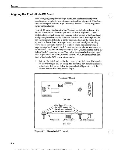
Figure 6-1 1 shows the layout of the <strong>Tsunami</strong> photodiode pc board. It is<br />
located directly over the beam splitter as shown in Figure 6-12. The<br />
photodiode is a small, round can soldered to the bottom of the board and,<br />
to align the photodiode to the reference beam from the beam splitter, the<br />
pc board is adjusted slightly to center the photodiode in the beam. Looking<br />
at the pc board from the output bezel, note that the right mounting<br />
screw passes through a narrow slot to allow lateral movement while a<br />
large rectangular slot under the left mounting screw allows movement in<br />
all directions. The photodiode is called out as CR1 and is located just to the<br />
right of the left mounting screw. To monitor the photodiode output signal<br />
level as you move the board, observe the PHOTODIODE indicator on the<br />
front of the Model 3955 electronics module.<br />
1. Refer to Table 6-1 and verify the correct photodiode board is installed<br />
for the wavelength you are using. The assembly part number is located<br />
in the lower left comer below the photodiode (Figure 6-1 1). If the<br />
correct board is installed, skip to step 3.<br />
Photodiode PC Board<br />
rt- - - - -11<br />
J3<br />
1 I----- 16<br />
I-----, 3930<br />
C_RI J 1<br />
---<br />
[,-\I<br />
@ :-;.------. I\ ,I<br />
[Number(<br />
1-= i<br />
I<br />
I<br />
I<br />
3955<br />
I<br />
I<br />
---<br />
.------a 1,-\1<br />
I\ ,I<br />
J<br />
Top View<br />
J2<br />
Photodiode<br />
J1 Connect<br />
Side View<br />
Figure 6-11: Photodiode PC board


