

Tsunami - Beckman Institute Laser Resource Center
Tsunami - Beckman Institute Laser Resource Center
Tsunami - Beckman Institute Laser Resource Center

You also want an ePaper? Increase the reach of your titles
YUMPU automatically turns print PDFs into web optimized ePapers that Google loves.
I I I Ill 1 I I Nllfl ll l l I I Ill I11 1 1, ' I ill ! 1 Ill I i I I iU I I I I<br />
Controls. Indicators and Connections<br />
# \<br />
PULSING<br />
Gn<br />
TEMPERANRE<br />
MODE LOCKER<br />
TEMPERATURE<br />
STATUS 1<br />
Gll POSITION<br />
0<br />
J<br />
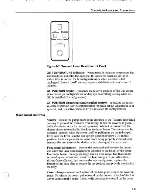
Figure 4-2: <strong>Tsunami</strong> <strong>Laser</strong> Head Control Panel<br />
GTI TEMPERATURE indicator-when green, it indicates temperature has<br />
stabilized; red indicates the opposite. It flashes red when no GTI is installed<br />
(this is normal for fs configuration) or when its cable is left<br />
unplugged. From a "cold" start-up, expect a stabilization time of about 15<br />
minutes.<br />
GTI POSITION display-indicates the relative position of the GTI dispersion<br />
control (ps configuration), or displays an arbitrary setting when no<br />
GTI is installed (fs configuration).<br />
GTI POSITION dispersion compensation control+ptimizes the group<br />
velocity dispersion (GVD) compensation for pulse length adjustment in ps<br />
systems, and is inactive when no GTI is installed (fs configuration).<br />
Mechanical Controls<br />
Shutter-blocks the pump beam at the entrance to the <strong>Tsunami</strong> laser head<br />
housing to prevent the <strong>Tsunami</strong> from lasing. When the cover is in place, it<br />
holds the shutter open for normal operation. When it is is removed, the<br />
shutter closes automatically, blocking the input beam. The shutter can be<br />
defeated (opened) when the cover is off by pulling up on the red-tipped<br />
lever until the lever is in the full upright position (Figure 2-3). In this<br />
position, the lever prevents the cover from being properly installed, and<br />
reminds the user to reset the shutter before closing up the laser head.<br />
Foot height adjustment-two on the input end and one one the output<br />
end allow the laser head height to be adjusted to the height of the pump<br />
laser input beam. The legs are large screws with swivel feet that can be<br />
screwed up and down from inside the laser using a 5/32 in. Allen (hex)<br />
driver. Once adjusted, jam nuts on the legs are tightened against the<br />
bottom of the base plate to secure the set position and provide mechanical<br />
stability.<br />
Cover clamps--one on each corner of the base plate, secure the cover in<br />
place. To release the cover, pull outward on the bottom of each of the four<br />
cover latches until it snaps. Then, while pressing downward on the cover


