

Tsunami - Beckman Institute Laser Resource Center
Tsunami - Beckman Institute Laser Resource Center
Tsunami - Beckman Institute Laser Resource Center

Create successful ePaper yourself
Turn your PDF publications into a flip-book with our unique Google optimized e-Paper software.
<strong>Tsunami</strong><br />
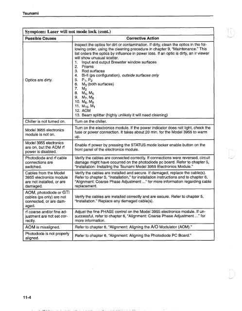
Symptom: <strong>Laser</strong> will not mode lock (cont.)<br />
Possible Causes<br />
Optics are dirty.<br />
Chiller is not turned on.<br />
3955 electronics<br />
module is not on.<br />
Model 3955 electronics<br />
are On' but the rf<br />
power is disabled.<br />
Photodiode and rf cable<br />
connections are<br />
switched.<br />
Cables from the Model<br />
3955 electronics module<br />
are not installed, or are<br />
damaged.<br />
AOM, photodiode or GTI<br />
cables (ps only) are not<br />
connected, or are damaged.<br />
rf coarse and/or fine adjustment<br />
are not set correctly.<br />
AOM is misaligned.<br />
Photodiode is<br />
aligned.<br />
Corrective Action<br />
Inspect the optics for dirt or contamination. If dirty, clean the optics in the following<br />
order, using the cleaning procedure in chapter 9, "Maintenance." This<br />
list orders the optics by influence in power loss. If an optic is dirty, an ir viewer<br />
will show unusual scatter.<br />
1. Input and output Brewster window surfaces<br />
2. Prisms<br />
3. Rod surfaces<br />
4. Bi-fi (ps configuration), outside surfaces only<br />
5. PI, P2<br />
6. M3 (both surfaces)<br />
7. M2<br />
8. M41 M5<br />
9. M7, M8<br />
10. Ms, M'J<br />
11. Ml0, M1<br />
12. AOM<br />
13. Beam splitter (highly unlikely it will need cleaning)<br />
Turn on the chiller.<br />
Turn on the electronics module. If the power indicator does not light, check the<br />
fuse or power connection. It takes about 20 min. for the Model 3955 to warm<br />
UP.<br />
Enable rf power by pressing the STATUS mode locker enable button on the<br />
front panel of the electronics module.<br />
Verify the cables are connected correctly. If connections were reversed, circuit<br />
damage might have occurred on the photodiode pc board. Refer to chapter 5,<br />
"Installation: Installing the <strong>Tsunami</strong> Model 3955 Electronics Module."<br />
Verify the cables are installed and secure. If damaged, replace the cable(s).<br />
Refer to chapter 5, "lnstallation," for installation instructions and to chapter 6,<br />
"Alignment: Coarse Phase Adjustment ..." for more information regarding cable<br />
replacement.<br />
Verify the cables are installed correctly and are secure. Refer to chapter 5,<br />
"lnstallation." Replace any damaged cable(s).<br />
Adjust the fine PHASE control on the Model 3955 electronics module. If unsuccessful,<br />
refer to chapter 6, "Alignment: Coarse Phase Adjustment ..." for<br />
more information.<br />
Refer to chapter 6, "Alignment: Aligning the A10 Modulator (AOM)."<br />
properly Refer to chapter 6, 'Alignment: Aligning the Photodiode PC Board.''


