

Tsunami - Beckman Institute Laser Resource Center
Tsunami - Beckman Institute Laser Resource Center
Tsunami - Beckman Institute Laser Resource Center

You also want an ePaper? Increase the reach of your titles
YUMPU automatically turns print PDFs into web optimized ePapers that Google loves.
Maintenance<br />
---<br />
I/<br />
A10 Modulator (AOM)<br />
The AOM is a very delicate, electrical acousto-optic device, and must be disconnected<br />
from the laser head pc board and removed from the laser head<br />
for cleaning. Do not clean it unless absolutely necessary.<br />
DANGER: HIGH VOLTAGE<br />
The pc board on the floor of the laser head contains high voltage to<br />
drive the GTI (ps configuration). Turn off the Model 3955 electronics<br />
module to disable this board.<br />
1. Close the pump laser shutter.<br />
2. Turn off the Model 3955 electronics.<br />
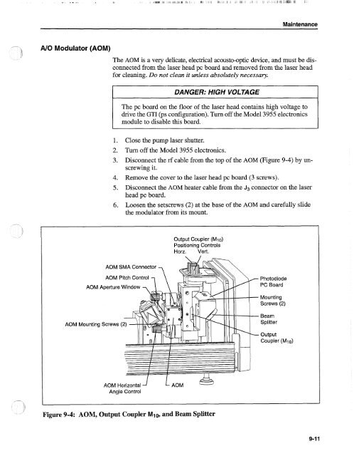
3. Disconnect the rf cable from the top of the AOM (Figure 9-4) by unscrewing<br />
it.<br />
4. Remove the cover to the laser head pc board (3 screws).<br />
5. Disconnect the AOM heater cable from the Jg connector on the laser<br />
head pc board.<br />
6. Loosen the setscrews (2) at the base of the AOM and carefully slide<br />
the modulator from its mount.<br />
Output Coupler (MIo)<br />
Positioning Controls<br />
Horz. Vert.<br />
AOM SMA Connector<br />
AOM Pitch Control<br />
AOM Aperture Window<br />
AOM Mounting Screws (<br />
Photodiode<br />
PC Board<br />
Mounting<br />
Screws (2)<br />
Beam<br />
Splitter<br />
Output<br />
Coupler (Mio)<br />
--<br />
I<br />
Angle Control<br />
Figure 9-4: AOM, Output Coupler Mlo, and Beam Splitter


