

Tsunami - Beckman Institute Laser Resource Center
Tsunami - Beckman Institute Laser Resource Center
Tsunami - Beckman Institute Laser Resource Center

Create successful ePaper yourself
Turn your PDF publications into a flip-book with our unique Google optimized e-Paper software.
I II I j Irl Ill lli Ill I t I I LJ I 1 I ULI I I<br />
Operation<br />
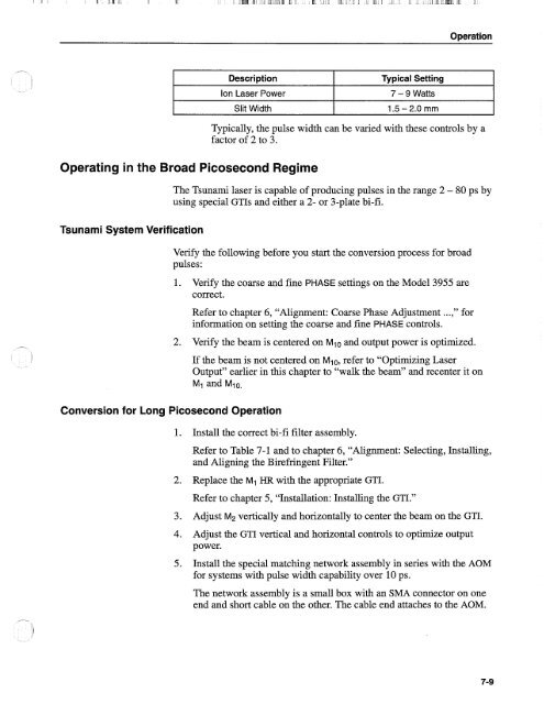
Description<br />
Ion <strong>Laser</strong> Power<br />
Slit Width<br />
Operating in the Broad Picosecond Regime<br />
<strong>Tsunami</strong> System Verification<br />
Typical Setting<br />
7 - 9 Watts<br />
1.5 - 2.0 mm<br />
Typically, the pulse width can be varied with these controls by a<br />
factor of 2 to 3.<br />
The <strong>Tsunami</strong> laser is capable of producing pulses in the range 2 - 80 ps by<br />
using special GTIs and either a 2- or 3-plate bi-fi.<br />
Verify the following before you start the conversion process for broad<br />
pulses:<br />
Conversion for Long Picosecond Operation<br />
1. Verify the coarse and fine PHASE settings on the Model 3955 are<br />
correct.<br />
Refer to chapter 6, "Alignment: Coarse Phase Adjustment ...," for<br />
information on setting the coarse and fine PHASE controls.<br />
2. Verify the beam is centered on Mlo and output power is optimized.<br />
If the beam is not centered on Mlo, refer to "Optimizing <strong>Laser</strong><br />
Output" earlier in this chapter to "walk the beam" and recenter it on<br />
M1 and Mio.<br />
1. Install the correct bi-fi filter assembly.<br />
Refer to Table 7-1 and to chapter 6, "Alignment: Selecting, Installing,<br />
and Aligning the Birefringent Filter."<br />
2. Replace the MI HR with the appropriate GTI.<br />
Refer to chapter 5, "Installation: Installing the GTI."<br />
3. Adjust M2 vertically and horizontally to center the beam on the GTI.<br />
4. Adjust the GTI vertical and horizontal controls to optimize output<br />
power.<br />
5. Install the special matching network assembly in series with the AOM<br />
for systems with pulse width capability over 10 ps.<br />
The network assembly is a small box with an SMA connector on one<br />
end and short cable on the other. The cable end attaches to the AOM.


