

Tsunami - Beckman Institute Laser Resource Center
Tsunami - Beckman Institute Laser Resource Center
Tsunami - Beckman Institute Laser Resource Center

Create successful ePaper yourself
Turn your PDF publications into a flip-book with our unique Google optimized e-Paper software.
<strong>Tsunami</strong><br />
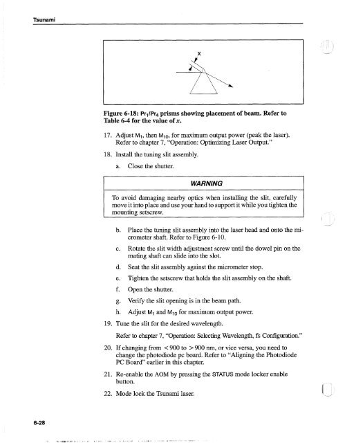
Figure 6-18: Pr1/Pr4 prisms showing placement of beam. Refer to<br />
Table 6-4 for the value of x.<br />
17. Adjust MI, then M1 0, for maximum output power (peak the laser).<br />
Refer to chapter 7, "Operation: Optimizing <strong>Laser</strong> Output."<br />
18. Install the tuning slit assembly.<br />
a. Close the shutter.<br />
WARNING<br />
To avoid damaging nearby optics when installing the slit, carefully<br />
move it into place and use your hand to support it while you tighten the<br />
mounting setscrew.<br />
b. Place the tuning slit assembly into the laser head and onto the micrometer<br />
shaft. Refer to Figure 6-10.<br />
c. Rotate the slit width adjustment screw until the dowel pin on the<br />
mating shaft can slide into the slot.<br />
d. Seat the slit assembly against the micrometer stop.<br />
e. Tighten the setscrew that holds the slit assembly on the shaft.<br />
f. Open the shutter.<br />
g. Venfy the slit opening is in the beam path.<br />
h. Adjust MI and M10 for maximum output power.<br />
19. Tune the slit for the desired wavelength.<br />
-- "-<br />
Refer to chapter 7, "Operation: Selecting Wavelength, fs Configuration."<br />
20. If changing from < 900 to > 900 nm, or vice versa, you need to<br />
change the photodiode pc board. Refer to "Aligning the Photodiode<br />
PC Board" earlier in this chapter.<br />
21. Re-enable the AOM by pressing the STATUS mode locker enable<br />
button.<br />
22. Mode lock the <strong>Tsunami</strong> laser.


