- Page 1:
Tsunami Mode-locked Ti: sapphire La
- Page 5 and 6:
Table of Contents ... Preface .....
- Page 7 and 8:
Table of Contents . Chapter 6: Alig
- Page 9 and 10:
Table of Contents Chapter 10: Optio
- Page 11 and 12:
Table of Contents Figure 4-7: Typic
- Page 13 and 14:
Table of Contents Figure A-6: The f
- Page 15:
Warning Conventions The following w
- Page 19:
List of Abbreviations Used in this
- Page 22 and 23:
Tsunami Figure 1-1: The Tsunami Las
- Page 25 and 26:
Chapter 2 Laser Safety DANGER The T
- Page 27 and 28:
Laser Safety CA UTlON Use of contro
- Page 29 and 30:
1 1 1 Il I 11 I I 1 El l11111II~Ill
- Page 31 and 32:
Chapter 3 Laser Description General
- Page 33 and 34:
Laser Description growth techniques
- Page 35 and 36:
Laser Description - AOM OC n Fast P
- Page 37 and 38:
Laser Description 2.4 - 2.2 - 2.0 -
- Page 39 and 40:
I IIIIIN III I I 1 I 11111 i~ I I I
- Page 41 and 42:
I II li I I I i 1 il I 1 11 I 1 1 1
- Page 43:
I Laser Description . Outline Dimen
- Page 46 and 47:
Tsunami Input Bezel Connections The
- Page 48 and 49:
Tsunami Opto-Mechanical Controls Al
- Page 50 and 51:
Tsunami Blue Knob: Vertical Adjust
- Page 52 and 53:
~lpl~ f \ Tsunami Opto-Mechanical C
- Page 54 and 55:
Tsunami Figure 4-7: 'Qpical MONITOR
- Page 56 and 57:
Tsunami r @ Spectra-Physics - - 4 2
- Page 58 and 59:
Tsunami Laser Installation Installi
- Page 60 and 61:
Tsunami Setting up the Routing Mirr
- Page 62 and 63:
Tsunami Aligning the Tsunami Laser
- Page 64 and 65:
Tsunami A -----------. PHOTODIODE O
- Page 66 and 67:
Tsunami Removing the Purge Line fro
- Page 68 and 69:
Tsunami Motorized Mount "Dm-shaped
- Page 70 and 71:
Tsunami I I J3 3930 - - - #,-,I --J
- Page 72 and 73:
Tsunami CA UTION DO NOT remove or a
- Page 74 and 75:
Tsunami Refer to the tables at the
- Page 76 and 77:
Tsunami b. Move the stage by hand a
- Page 78 and 79:
Tsunami There will be one or two re
- Page 80 and 81:
Tsunami Figure 6-9: The Slit Contro
- Page 82 and 83:
Tsunami b. Place a white card with
- Page 84 and 85:
Tsunami Aligning the Photodiode PC
- Page 86 and 87:
Tsunami To measure pulses, use a Sp
- Page 88 and 89:
Tsunami pulses, adjust the coarse c
- Page 90 and 91:
Tsunami Selecting, Installing, and
- Page 92 and 93:
Tsunami Unless you are certain the
- Page 94 and 95:
Tsunami Prism Translation Adjust Fi
- Page 96 and 97:
Tsunami i. Route the GTI heater cab
- Page 98 and 99:
Tsunami Figure 6-18: Pr1/Pr4 prisms
- Page 100 and 101:
Tsunami Converting Between fs and p
- Page 102 and 103:
Tsunami b. Using an ir viewer, adju
- Page 104 and 105:
Tsunami g. Open the shutter. 15. Al
- Page 106 and 107:
Tsunami 10. Move Prl and Pr4 into t
- Page 108 and 109:
Tsunami 21. Mode lock Tsunami. Refe
- Page 110 and 111:
I " n 3 1 ' ! ' I . I 8 8 8 " t 8 0
- Page 112 and 113:
Tsunami recommend using 99.999% pur
- Page 114 and 115:
Tsunami Mode Locking the Laser 6. W
- Page 116 and 117:
Tsunami - - - 710 nrn - - 790 nrn -
- Page 118 and 119:
4 Tsunami Beam % 2 mm (0.08 in.) Pr
- Page 120 and 121:
Tsunami Table 7-1: Bi-fi Selection
- Page 123 and 124:
I I1 ! I : I I I ill 8 I !Il! I1I l
- Page 125 and 126:
Lok-to-Clock Electronics LEVEL cont
- Page 127 and 128:
Lok-to-Clock Electronics AOM M5f-4
- Page 129 and 130:
Lok-to-Clock Electronics Installing
- Page 131 and 132:
I I1 I i l l I iil 111 ,111 Ill ,il
- Page 133 and 134:
P Lok-to-Clock Electronics Model 20
- Page 135 and 136:
I 1 1 I 1~~~ 11 I 1 1 1 1 .III :ill
- Page 137 and 138:
Lok-to-Clock Electronics Figure 8-9
- Page 139:
I I1 I l I 1 bll Lok-to-Clock Elect
- Page 142 and 143:
Tsunami "Clean" is a relative descr
- Page 144 and 145:
Tsunami Figure 9-1: Drop and Drag M
- Page 146 and 147:
Tsunami With the exception of pump
- Page 148 and 149:
Tsunami On rare occasions, the lowe
- Page 150 and 151:
Tsunami 8. Open the pump laser shut
- Page 152 and 153:
Tsunami 7. Remove the screws (4) ho
- Page 154 and 155: Tsunami DryJClean Flow Adjust Nitro
- Page 156 and 157: Tsunami diode such as the Model 393
- Page 158 and 159: €968-PEP0 ES68-PEP0 PS68-PEP0 ES6
- Page 160 and 161: Tsunami Check marks indicate which
- Page 162 and 163: Tsunami Table 10-11: GTI and Bi-Pi
- Page 164 and 165: Tsunami Generic Troubleshooting (No
- Page 166 and 167: Tsunami Symptom: Laser will not mod
- Page 168 and 169: Tsunami Symptom: Unable to mode loc
- Page 170 and 171: Tsunami Symptom: Unable to mode loc
- Page 172 and 173: Tsunami Symptom: Cannot see individ
- Page 174 and 175: Tsunami Symptom: PZT oscillates whe
- Page 177 and 178: I I ill ; I l l I I lll.l1 I I I *
- Page 179 and 180: I I 111 il I iil i lllill ll I I ll
- Page 181 and 182: I I il : I I I 1 I Appendix A Mode
- Page 183 and 184: Mode Locking is chosen to be the sa
- Page 185 and 186: I I 0 I I 1 I )I Ulllllll ill I Mod
- Page 187 and 188: Mode Locking SPM will, thus, broade
- Page 189 and 190: Mode Locking The net intracavity GV
- Page 191 and 192: Appendix B Pulse Width Measurement
- Page 193 and 194: I I 0 I I 1 1 LI I lillll Ill I!,ll
- Page 195 and 196: Pulse Width Measurement -% GVD Comp
- Page 197 and 198: I I I I I I I I ti 911 I1 I Pulse W
- Page 199 and 200: I I I I I I B I IL 1 1 i 1111 I L I
- Page 201 and 202: I I 0 I I 1 1 L I I Pulse Width Mea
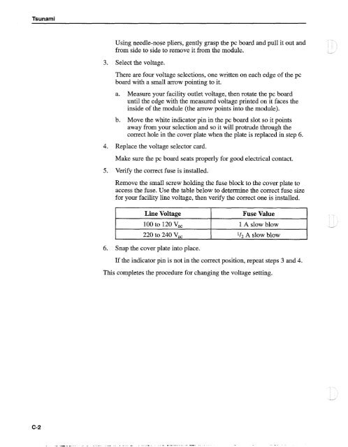
- Page 203: Appendix C Setting the Line Voltage
- Page 207 and 208: Material Safety Data Sheets MATERIA
- Page 209 and 210: I I I 1 r $1 I Bill II I I I I Ill
- Page 211 and 212: Material Safety Data Sheets MATERIA