Tsunami - Beckman Institute Laser Resource Center
Tsunami - Beckman Institute Laser Resource Center
Tsunami - Beckman Institute Laser Resource Center
You also want an ePaper? Increase the reach of your titles
YUMPU automatically turns print PDFs into web optimized ePapers that Google loves.
<strong>Tsunami</strong><br />
Input Bezel Connections<br />
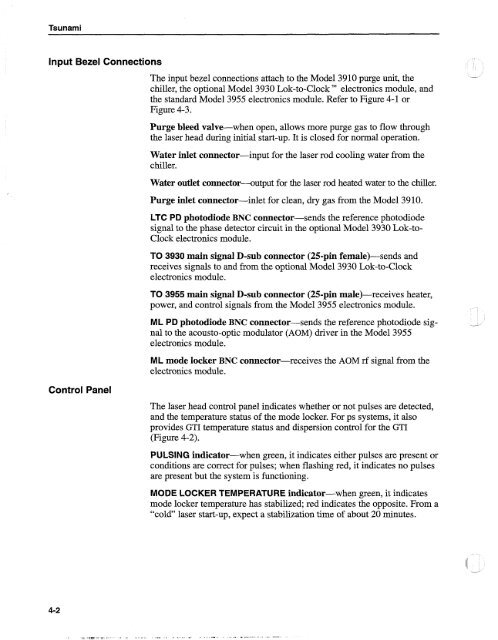
The input bezel connections attach to the Model 3910 purge unit, the -<br />
chiller, the optional Model 3930 Lok-to-ClockTM electronics module, and<br />
the standard Model 3955 electronics module. Refer to Figure 4-1 or<br />
Figure 4-3.<br />
Purge bleed valve-when open, allows more purge gas to flow through<br />
the laser head during initial start-up. It is closed for normal operation.<br />
Water inlet connector-input<br />
chiller.<br />
Water outlet connector-+utput<br />
for the laser rod cooling water from the<br />
for the laser rod heated water to the chiller.<br />
Purge inlet connector-inlet for clean, dry gas from the Model 3910.<br />
LTC PD photodiode BNC connector-sends the reference photodiode<br />
signal to the phase detector circuit in the optional Model 3930 Lok-to-<br />
Clock electronics module.<br />
TO 3930 main signal D-sub connector (25-pin female)-sends and<br />
receives signals to and from the optional Model 3930 Lok-to-Clock<br />
electronics module.<br />
TO 3955 main signal D-sub connector (25-pin male)-receives heater,<br />
power, and control signals from the Model 3955 electronics module.<br />
ML PD photodiode BNC connector-sends the reference photodiode sig- -<br />
nal to the acousto-optic modulator (AOM) driver in the Model 3955<br />
electronics module.<br />
ML mode locker BNC connector-receives<br />
electronics module.<br />
the AOM rf signal from the<br />
Control Panel<br />
The laser head control panel indicates whether or not pulses are detected,<br />
and the temperature status of the mode locker. For ps systems, it also<br />
provides GTI temperature status and dispersion control for the GTI<br />
(Figure 4-2).<br />
PULSING indicator-when green, it indicates either pulses are present or<br />
conditions are correct for pulses; when flashing red, it indicates no pulses<br />
are present but the system is functioning.<br />
MODE LOCKER TEMPERATURE indicator-when green, it indicates<br />
mode locker temperature has stabilized; red indicates the opposite. From a<br />
"cold" laser start-up, expect a stabilization time of about 20 minutes.


