Tsunami - Beckman Institute Laser Resource Center
Tsunami - Beckman Institute Laser Resource Center
Tsunami - Beckman Institute Laser Resource Center
Create successful ePaper yourself
Turn your PDF publications into a flip-book with our unique Google optimized e-Paper software.
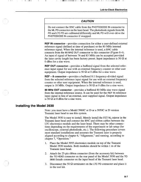
Lok-to-Clock Electronics<br />
Installing the Model 3930<br />
CAUTION<br />
Do not connect the BNC cable from the PHOTODIODE IN connector to<br />
the ML PD connector on the laser head. The photodiode signals from ML<br />
PD and LTC PD are calibrated differently and ML PD will over-drive the<br />
PHOTODIODE IN connector if swapped.<br />
REF IN connector-provides connection for either a user-defined external<br />
reference signal (defined at time of purchase) or the 80 MHz internal<br />
reference signal. When the internal reference is used, a BNC cable<br />
connects from the 80 MHz OUT connector to this connector (Figure 8-4).<br />
An input rf signal of between 76 and 83 MHz can be accepted provided<br />
the laser cavity length has been factory preset. Input impedance is 50 Q at<br />
0 dBm for a sine wave.<br />
REF OUT connector-provides a buffered signal from the selected reference<br />
input signal for use with an external frequency counter or other user<br />
equipment. Output impedance is 50 Q at 0 dBm for a sine wave.<br />
REF + 8 connector-provides a buffered 8:l frequency-divided signal<br />
from the selected reference input signal for use with an external frequency<br />
counter or other user equipment. When the internal reference is used,<br />
output is 10 MHz. Output impedance is 50 Q at 0 dBm for a sine wave.<br />
80 MHz OUT connector-provides a buffered 80 MHz sine wave signal<br />
from the internal reference source. It can be used for the REF IN reference<br />
input signal in lieu of an external, user-supplied signal. Output impedance<br />
is 50 Q at 0 dBm for a sine wave.<br />
Note: you must have a Model 3960C or D or a 39506 or D version<br />
<strong>Tsunami</strong> laser head to use this system.<br />
The Model 3930 is easy to install. Merely install the PZT M4 mirror in the<br />
<strong>Tsunami</strong> laser head and connect the BNC and ribbon cables between the<br />
LTC electronics module and the laser head. There may be other connections<br />
depending on the requirements of the experiment or lab setup (for<br />
oscilloscope, external photodiode, etc.). The following procedure covers<br />
most standard installations and assumes the <strong>Tsunami</strong> laser is properly<br />
aligned according to chapter 6, "Alignment," and running. according to<br />
chapter 7, "Operation."<br />
1. Place the Model 3955 electronics module on top of the <strong>Tsunami</strong><br />
Model 3930 module. Both modules should be within 1 m of the<br />
<strong>Tsunami</strong> laser head.<br />
2. Attach the 25-pin ribbon connector (from the accessory kit) between<br />
the TO HEAD connector on the rear panel of the Model 3930 and the TO<br />
3930 female connector on the input bezel of the <strong>Tsunami</strong> laser head.<br />
3. Disconnect the 50 Q terminator on the LTC PD connector and place it<br />
in the tool kit.


