

Tsunami - Beckman Institute Laser Resource Center
Tsunami - Beckman Institute Laser Resource Center
Tsunami - Beckman Institute Laser Resource Center

You also want an ePaper? Increase the reach of your titles
YUMPU automatically turns print PDFs into web optimized ePapers that Google loves.
Lok-to-Clock Electronics<br />
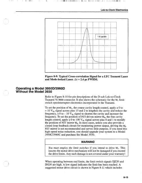
Figure 8-9: Typical Cross-correlation Signal for a LTC <strong>Tsunami</strong> <strong>Laser</strong><br />
and Mode-locked <strong>Laser</strong>. AT = 2.4 ps FWHM.<br />
Operating a Model 3950Dl3960D<br />
Without the Model 3930<br />
Refer to Figure 8-10 for pin descriptions of the D-sub Lok-to-Clock<br />
<strong>Tsunami</strong> To 3930 connector. It also shows the schematic for the Mi limit<br />
switch optointermptor electronics incorporated in the <strong>Tsunami</strong>.<br />
To set the position of Mi, the coarse cavity length control, apply a 0 to<br />
+ 10 Vdc signal across pins 13 and 2 to lengthen the cavity and reduce the<br />
frequency, a 0 to - 10 Vdc signal to shorten the cavity and increase the<br />
frequency. To set the position of PZT-driven mirror M4, the fine cavity<br />
length control, apply a 0 to 100 Vdc signal across pins 8 and 1 to modify<br />
the position of PZT mirror M4. In most cases, unless you also provide a<br />
closed-loop feedback circuit for monitoring power output, driving the M4<br />
PZT mirror is not recommended and serves little purpose. If you need this<br />
high-speed noise reduction, you should upgrade your system to a Model<br />
3950Cl3960C and purchase the Model 3930.<br />
WARNING<br />
You must employ the limit switches if you intend to drive Mi. This<br />
insures the motor drive mechanism will not be damaged if you exceed<br />
the drive limits. Any such damage is not covered under your warranty!<br />
When operating between end limits, the limit switch signals UpLim and<br />
DnLim are high. A low signal indicates the limit has been reached. A<br />
suggested motor drive circuit is shown in Figure 8-1 1 which includes


