Tsunami - Beckman Institute Laser Resource Center
Tsunami - Beckman Institute Laser Resource Center
Tsunami - Beckman Institute Laser Resource Center
Create successful ePaper yourself
Turn your PDF publications into a flip-book with our unique Google optimized e-Paper software.
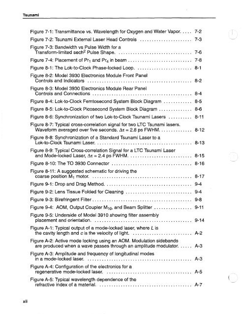
<strong>Tsunami</strong><br />
Figure 7-1 : Transmittance vs . Wavelength for Oxygen and Water Vapor ..... 7-2<br />
I<br />
Figure 7-2: <strong>Tsunami</strong> External <strong>Laser</strong> Head Controls ...................... 7-3 .<br />
Figure 7-3: Bandwidth vs Pulse Width for a<br />
Transform-limited sech2 Pulse Shape ................................ 7-6<br />
Figure 7-4: Placement of Prl and Pr4 in beam ........................... 7-8<br />
Figure 8-1 : The Lok-to-Clock Phase-locked Loop ........................ 8-1<br />
Figure 8-2: Model 3930 Electronics Module Front Panel<br />
Controls and Indicators ............................................ 8-2<br />
Figure 8-3: Model 3930 Electronics Module Rear Panel<br />
Controls and Connections .......................................... 8-4<br />
Figure 8-4: Lok-to-Clock Femtosecond System Block Diagram ............ 8-5<br />
Figure 8-5: Lok-to-Clock Picosecond System Block Diagram .............. 8-6<br />
Figure 8-6: Synchronization of two Lok-to-Clock <strong>Tsunami</strong> <strong>Laser</strong>s .......... 8-11<br />
Figure 8-7: Typical cross-correlation signal for two LTC <strong>Tsunami</strong> lasers .<br />
Waveform averaged over five seconds . AT = 2.8 ps FWHM .............. 8-12<br />
Figure 8-8: Synchronization of a Standard <strong>Tsunami</strong> <strong>Laser</strong> to a<br />
Lok-to-Clock <strong>Tsunami</strong> <strong>Laser</strong> ......................................... 8-13<br />
Figure 8-9: Typical Cross-correlation Signal for a LTC <strong>Tsunami</strong> <strong>Laser</strong><br />
and Mode-locked <strong>Laser</strong>. AT = 2.4 ps FWHM ........................... 8-15<br />
Figure 8-1 0: The TO 3930 Connector .................................. 8-16<br />
Figure 8-11 : A suggested schematic for driving the<br />
coarse position MI motor ........................................... 8-17<br />
Figure 9-1: Drop and Drag Method ..................................... 9-4<br />
Figure 9-2: Lens Tissue Folded for Cleaning ............................ 9-4<br />
Figure 9-3: Birefringent Filter .......................................... 9-8<br />
Figure 9-4: AOM. Output Coupler MlO. and Beam Splitter ................ 9-11<br />
Figure 9-5: Underside of Model 391 0 showing filter assembly<br />
placement and orientation .......................................... 9-14<br />
Figure A-1 : Typical output of a mode-locked laser. where L is<br />
the cavity length and c is the velocity of light .......................... A-2<br />
Figure A-2: Active mode locking using an AOM . Modulation sidebands<br />
are produced when a wave passes through an amplitude modulator ...... A-3<br />
Figure A-3: Amplitude and frequency of longitudinal modes<br />
in a mode-locked laser ............................................. A-3<br />
Figure A-4: Configuration of the electronics for a<br />
regenerative mode-locked laser ..................................... A-5<br />
Figure A-5: Typical wavelength dependence of the<br />
refractive index of a material ........................................ A-7<br />
xii


