

Tsunami - Beckman Institute Laser Resource Center
Tsunami - Beckman Institute Laser Resource Center
Tsunami - Beckman Institute Laser Resource Center

Create successful ePaper yourself
Turn your PDF publications into a flip-book with our unique Google optimized e-Paper software.
Alignment<br />
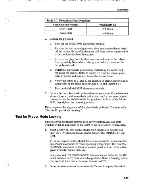
Table 6-1: Photodiode Part Numbers<br />
Assembly Part Number<br />
0448- 1420<br />
0448-3910<br />
Wavelength (A)<br />
< 900 nm<br />
> 900 nm<br />
2. Change the pc board.<br />
Test for Proper Mode Locking<br />
a. Turn off the Model 3955 electronics module.<br />
b. Remove the two mounting screws, then gently raise the pc board<br />
off the mount. Be careful, there are still three cables connected to<br />
it. Do not lose the five (5) washers.<br />
c. Remove the plug from J1, then unscrew and remove the cables<br />
from J2 and J3. Note which cable goes to which connector. Set<br />
the pc board aside.<br />
d. Install the appropriate pc board by reattaching the cables and<br />
replacing the screws. Refer to Figure 6-11 for the correct placement<br />
of cables and washers. Leave the screws loose.<br />
e. Verify the cables to J2 and J3 are attached to their respective BNC<br />
connectors on the input bezel (Figure 6-11 and Figure 4-1).<br />
f. Turn on the Model 3955 electronics module.<br />
3. Loosen the two photodiode pc board mounting screws if you have not<br />
already done so, and move the board around until a maximum signal<br />
is observed on the PHOTODIODE bar graph on the front of the Model<br />
3955, then tighten the mounting screws.<br />
This completes the alignment of the photodiode pc board. Continue with<br />
"Test for Proper Mode Locking."<br />
This following procedure assures good cavity performance and tests<br />
whether or not an alignment of the AOM in the next section is necessary.<br />
1. If not already on, turn on the Model 3955 electronics module and<br />
push the STATUS mode locker enable button. The ENABLE LED will<br />
light.<br />
If you just turned on the Model 3955, allow about 20 minutes for the<br />
heaters and electronics to reach operating temperature. The two TEM-<br />
PERATURE indicators on the laser control panel will turn from red to<br />
green when the heaters stabilize.<br />
Aflashing red GTI TEMPERATURE indicator means either (a) the GTI<br />
is not installed or (b) there is a cable problem. Note: a flashing indicator<br />
is normal for a fs laser because there is no GTI.<br />
2. Set up an autocorrelator to measure the <strong>Tsunami</strong> output pulse width.


