

Tsunami - Beckman Institute Laser Resource Center
Tsunami - Beckman Institute Laser Resource Center
Tsunami - Beckman Institute Laser Resource Center

Create successful ePaper yourself
Turn your PDF publications into a flip-book with our unique Google optimized e-Paper software.
- . Ill I L I I Lli I 3 1l 11 I<br />
Installation<br />
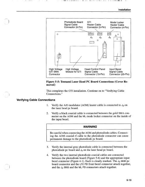
Photodiode Board GTI Mode Locker<br />
Signal Cable Heater Cable Heater Cable<br />
Connector (6-Pin) Connector (5-Pin) Connector (4-Pin)<br />
High Voltage High Voltage Head Control Panel Input Bezel<br />
GTI SMA Module for GTI Signal Cable Signal Cable<br />
Connector Connector (10-Pin) Connector (25-Pin)<br />
Verifying Cable Connections<br />
Figure 5-5: <strong>Tsunami</strong> <strong>Laser</strong> Head PC Board Connections (Cover Removed)<br />
This completes the GTI installation. Continue on to "Verifying Cable<br />
Connections."<br />
1. Verify the A10 modulator (AOM) heater cable is connected to J3 on<br />
the laser head pc board.<br />
2. Verify a black coaxial cable is connected between the gold SMA connector<br />
on the AOM and the ML mode locker connector on the inside of<br />
the input bezel.<br />
WARNING<br />
Be careful when connecting the AOM and photodiode cables. Connecting<br />
the AOM coaxial rf cable to the photodiode connector can cause<br />
permanent damage to the photodiode pc board.<br />
3. Verify the internal gray photodiode cable is connected between the<br />
photodiode pc board and J4 on the laser head pc board.<br />
4. Verify the two internal photodiode coaxial cables are connected<br />
between the photodiode board (Figure 5-6) and the appropriate input<br />
bezel connector (Figure 4-1). Each is clearly marked. The J3 3930 pc<br />
board connector and the LTC PD front bezel connector attach together,<br />
and the J2 3955 and the ML PD connectors attach together.


