- Page 1:
EQUIPPED WITH BOBCAT INTERLOCK CONT
- Page 5 and 6:
FOREWORD . . . . . . . . . . . . .
- Page 7 and 8:
17. Inspect the air cleaner for dam
- Page 9 and 10:
SAFETY INSTRUCTIONS Instructions ar
- Page 11 and 12:
SERIAL NUMBER LOCATIONS Always use
- Page 13 and 14:
All 853 & 853H Bobcat loaders are e
- Page 15 and 16:
PREVENTIVE MAINTENANCE Page Number
- Page 17 and 18:
SERVICE SCHEDULE Maintenance work m
- Page 19 and 20:
TRANSPORTING THE LOADER Procedure A
- Page 21 and 22:
LIFT ARM SUPPORT DEVICE Never work
- Page 23 and 24:
OPERATOR CAB (Cont’d) Lowering th
- Page 25 and 26:
AIR CLEANER SERVICE Replacing Filte
- Page 27 and 28:
FUEL SYSTEM Fuel Specifications Use
- Page 29 and 30:
ENGINE LUBRICATION SYSTEM Checking
- Page 31 and 32:
ENGINE COOLING SYSTEM Cleaning the
- Page 33 and 34:
USING A BOOSTER BATTERY (Jump Start
- Page 35 and 36:
HYDRAULIC/HYDROSTATIC SYSTEM (Cont
- Page 37 and 38:
SPARK ARRESTOR MUFFLER Cleaning Pro
- Page 39 and 40:
FINAL DRIVE TRANSMISSION (CHAINCASE
- Page 41 and 42:
LUBRICATING THE LOADER (Cont’d) P
- Page 43 and 44:
REMOTE START SWITCH (Cont’d) Proc
- Page 45 and 46:
HYDRAULIC SYSTEM Page Number BUCKET
- Page 47 and 48:
1 FLUID RESERVOIR: Cap . . . . 15.5
- Page 49 and 50:
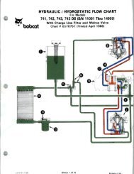
HYDRAULIC/HYDROSTATIC SCHEMATIC 853
- Page 51 and 52:
HYDRAULIC SYSTEM TROUBLESHOOTING Ch
- Page 53 and 54:
LIFT CYLINDER(S) Checking the Lift
- Page 55 and 56:
TILT CYLINDER Checking the Tilt Cyl
- Page 57 and 58:
HYDRAULIC CYLINDER Lift Cylinder Id
- Page 59 and 60:
HYDRAULIC CYLINDER (Cont’d) Disas
- Page 61 and 62:
HYDRAULIC CYLINDER (Cont’d) Disas
- Page 63 and 64:
HYDRAULIC CYLINDER (Cont’d) Assem
- Page 65 and 66:
HYDRAULIC CYLINDER (Cont’d) Assem
- Page 67 and 68:
MAIN RELIEF VALVE Checking the Main
- Page 69 and 70:
MAIN RELIEF VALVE (Cont’d) Remova
- Page 71 and 72:
DUAL PRESSURE MAIN RELIEF VALVE - 8
- Page 73 and 74:
DUAL PRESSURE MAIN RELIEF VALVE - 8
- Page 75 and 76:
SELECT VALVE (G.E.M. Block) 853H Ch
- Page 77 and 78:
HYDRAULIC CONTROL VALVE (Cont’d)
- Page 79 and 80:
HYDRAULIC CONTROL VALVE (Cont’d)
- Page 81 and 82:
HYDRAULIC CONTROL VALVE (Cont’d)
- Page 83 and 84:
HYDRAULIC CONTROL VALVE (Cont’d)
- Page 85 and 86:
HYDRAULIC CONTROL VALVE (Cont’d)
- Page 87 and 88:
HYDRAULIC CONTROL VALVE (Cont’d)
- Page 89 and 90:
HYDRAULIC CONTROL VALVE (Cont’d)
- Page 91 and 92:
HYDRAULIC CONTROL VALVE (Cont’d)
- Page 93 and 94:
HYDRAULIC PUMP Checking the Output
- Page 95 and 96:
HYDRAULIC PUMP (Cont’d) Parts Ide
- Page 97 and 98:
HYDRAULIC PUMP (Cont’d) Disassemb
- Page 99 and 100:
HYDRAULIC PUMP (Cont’d) Assembly
- Page 101 and 102:
HYDRAULIC PUMP (Double Gear) 853H C
- Page 103 and 104:
HYDRAULIC PUMP (Double Gear) 853H (
- Page 105 and 106:
HYDRAULIC PUMP (Double Gear) 853H (
- Page 107 and 108:
HYDRAULIC PUMP (Double Gear) 853H (
- Page 109 and 110:
HYDRAULIC PUMP (Double Gear) 853H (
- Page 111 and 112:
HYDRAULIC PUMP (Double Gear) 853H (
- Page 113 and 114:
HYDRAULIC FLUID RESERVOIR Removal a
- Page 115 and 116:
HYDRAULIC FILTER HOUSING Removal an
- Page 117 and 118:
PEDAL INTERLOCK LINKAGE Removal and
- Page 119 and 120:
Revised June 96 HYDROSTATIC SYSTEM
- Page 121 and 122:
TROUBLESHOOTING Chart The following
- Page 123 and 124:
FRONT PANEL Removal and Installatio
- Page 125 and 126:
STEERING LEVERS Disassembly and Ass
- Page 127 and 128:
STEERING LEVERS (Cont’d) Pre-Adju
- Page 129 and 130:
STEERING LEVERS (Cont’d) Adjustin
- Page 131 and 132:
STEERING LEVERS (Cont’d) Adjustin
- Page 133 and 134:
HYDROSTATIC MOTOR Removal and Insta
- Page 135 and 136:
HYDROSTATIC MOTOR (Cont’d) Disass
- Page 137 and 138:
HYDROSTATIC MOTOR (Cont’d) Disass
- Page 139 and 140:
HYDROSTATIC MOTOR (Cont’d) Disass
- Page 141 and 142:
HYDROSTATIC MOTOR (Cont’d) Assemb
- Page 143 and 144:
HYDROSTATIC MOTOR (Cont’d) 853, 8
- Page 145 and 146:
HYDROSTATIC PUMP Removal and Instal
- Page 147 and 148:
HYDROSTATIC PUMP (Cont’d) Repleni
- Page 149 and 150:
HYDROSTATIC PUMP (Cont’d) Parts I
- Page 151 and 152:
HYDROSTATIC PUMP (Cont’d) Parts I
- Page 153 and 154:
HYDROSTATIC PUMP (Cont’d) Hydraul
- Page 155 and 156:
HYDROSTATIC PUMP (Cont’d) Charge
- Page 157 and 158:
HYDROSTATIC PUMP (Cont’d) Disasse
- Page 159 and 160:
HYDROSTATIC PUMP (Cont’d) Disasse
- Page 161 and 162:
HYDROSTATIC PUMP (Cont’d) Disasse
- Page 163 and 164:
HYDROSTATIC PUMP (Cont’d) Disasse
- Page 165 and 166:
HYDROSTATIC PUMP (Cont’d) Inspect
- Page 167 and 168:
HYDROSTATIC PUMP (Cont’d) Assembl
- Page 169 and 170:
HYDROSTATIC PUMP (Cont’d) Assembl
- Page 171 and 172:
HYDROSTATIC PUMP (Cont’d) Assembl
- Page 173 and 174:
HYDROSTATIC PUMP (Cont’d) Assembl
- Page 175 and 176:
HYDROSTATIC PUMP (Cont’d) Assembl
- Page 177 and 178:
HYDROSTATIC PUMP (Cont’d) Hydraul
- Page 179 and 180:
HYDROSTATIC PUMP (Cont’d) Hydrost
- Page 181 and 182:
DRIVE BELT Adjusting the Drive Belt
- Page 183 and 184:
DRIVE BELT TENSIONER PULLEY Removal
- Page 185 and 186:
DRIVE BELT TENSIONER PULLEY (Cont
- Page 187 and 188:
DRIVE BELT TENSIONER PULLEY (Cont
- Page 189 and 190:
DRIVE BELT TENSIONER PULLEY (Cont
- Page 191 and 192:
OIL COOLER Removal and Installation
- Page 193 and 194:
DRIVE SYSTEM Page Number AXLE SEAL
- Page 195 and 196:
DRIVE SYSTEM PARKING BRAKE PEDAL Re
- Page 197 and 198:
PARKING BRAKE DISC Removal and Inst
- Page 199 and 200:
FRONT CHAINCASE COVER Removal and I
- Page 201 and 202:
AXLE SEAL (Cont’d) Removal and In
- Page 203 and 204:
AXLE, BEARINGS AND SPROCKET (Cont
- Page 205 and 206:
AXLE, BEARING AND SPROCKET (Cont’
- Page 207 and 208:
REDUCTION GEARCASE (Cont’d) Remov
- Page 209 and 210:
REDUCTION GEARCASE (Cont’d) Disas
- Page 211 and 212:
REDUCTION GEARCASE (Cont’d) Disas
- Page 213 and 214:
REDUCTION GEARCASE (Cont’d) Assem
- Page 215 and 216:
REDUCTION GEARCASE (Cont’d) Assem
- Page 217 and 218:
DRIVE CHAIN 853, 853H BICS Service
- Page 219 and 220:
MAIN FRAME Page Number BOB-TACH Bob
- Page 221 and 222:
MAIN FRAME SEAT BAR Removal and Ins
- Page 223 and 224:
SEAT BAR (Cont’d) Removal and Ins
- Page 225 and 226:
OPERATOR CAB GAS CYLINDER Removal a
- Page 227 and 228:
OPERATOR CAB Removal and Installati
- Page 229 and 230:
OPERATOR SEAT Removal and Installat
- Page 231 and 232:
BOB-TACH (Cont’d) Removal and Ins
- Page 233 and 234:
BOB-TACH (Cont’d) Bob-Tach Lever
- Page 235 and 236:
REAR GRILL Removal and Installation
- Page 237 and 238:
REAR DOOR (Cont’d) Hood Removal a
- Page 239 and 240:
FUEL TANK (Cont’d) Removal and In
- Page 241 and 242:
ELECTRICAL SYSTEM Page Number ALTER
- Page 274 and 275:
WIRE LEGEND NO.'s COLOR GAUGE PARTS
- Page 276 and 277:
WIRE LEGEND NO.'s COLOR GAUGE 12 Or
- Page 278 and 279:
ELECTRICAL SYSTEM TROUBLESHOOTING C
- Page 280 and 281:
BATTERY Removal and Installation Ba
- Page 282 and 283:
ALTERNATOR (Cont’d) Alternator Re
- Page 284 and 285:
ALTERNATOR (Cont’d) Disassembly a
- Page 286 and 287:
ALTERNATOR (Cont’d) Assembly Reve
- Page 288 and 289:
STARTER (Cont’d) Checking the Sta
- Page 290 and 291:
STARTER (Cont’d) Disassembly and
- Page 292 and 293:
STARTER (Cont’d) Cleaning and Ins
- Page 294 and 295:
FRONT LIGHTS Removal and Installati
- Page 296 and 297:
ENGINE SERVICE Page Number AIR CLEA
- Page 298 and 299:
ENGINE SERVICE TROUBLESHOOTING Char
- Page 300 and 301:
RADIATOR Removal and Installation O
- Page 302 and 303:
COOLANT RECOVERY TANK Removal and I
- Page 304 and 305:
AIR CLEANER HOUSING Removal and Ins
- Page 306 and 307:
BLOWER HOUSING/FAN GEARBOX (Cont’
- Page 308 and 309:
BLOWER FAN Removal and Installation
- Page 310 and 311:
FAN GEARBOX (Cont’d) Disassembly
- Page 312 and 313:
FAN GEARBOX (Cont’d) Disassembly
- Page 314 and 315:
FAN GEARBOX (Cont’d) Disassembly
- Page 316 and 317:
FAN GEARBOX (Cont’d) Assembly (Co
- Page 318 and 319:
FAN GEARBOX (Cont’d) Assembly (Co
- Page 320 and 321:
FAN GEARBOX (Cont’d) 853, 853H BI
- Page 322 and 323:
FAN GEARBOX (Cont’d) Checking Bac
- Page 324 and 325:
ENGINE (Cont’d) Removal and Insta
- Page 326 and 327:
ENGINE (Cont’d) Removal and Insta
- Page 328 and 329:
ENGINE (Cont’d) Removal and Insta
- Page 330 and 331:
ENGINE (Cont’d) Engine Mount Repl
- Page 332 and 333:
BELT SHIELD Removal and Installatio
- Page 334 and 335:
GLOW PLUGS Removal and Installation
- Page 336 and 337:
FUEL INJECTION PUMP (Cont’d) Remo
- Page 338 and 339:
FUEL INJECTION PUMP (Cont’d) Remo
- Page 340 and 341:
FUEL INJECTION PUMP (Cont’d) Timi
- Page 342 and 343:
FUEL INJECTOR NOZZLES (Cont’d) Re
- Page 344 and 345:
CYLINDER HEAD Removal and Installat
- Page 346 and 347:
VALVES, VALVE SEAT AND GUIDE Remova
- Page 348 and 349:
VALVES, VALVE SEAT AND GUIDE (Cont
- Page 350 and 351:
PISTON AND CONNECTING ROD Removal R
- Page 352 and 353:
PISTON AND CONNECTING ROD (Cont’d
- Page 354 and 355: PISTON AND CONNECTING ROD (Cont’d
- Page 356 and 357: CYLINDER LINERS Checking the Cylind
- Page 358 and 359: MAIN BEARINGS (Cont’d) Installati
- Page 360 and 361: CRANKSHAFT Removal and Installation
- Page 362 and 363: CRANKSHAFT GEAR Removal and Install
- Page 364 and 365: TIMING GEARCASE COVER Removal and I
- Page 366 and 367: IDLER GEAR AND HUB Removal Remove t
- Page 368 and 369: FUEL INJECTION PUMP IDLER GEAR Remo
- Page 370 and 371: TIMING GEARCASE 853, 853H BICS Serv
- Page 372 and 373: CAMSHAFT (Cont’d) Camshaft Bearin
- Page 374 and 375: OIL PAN Removal Remove the oil drai
- Page 376 and 377: OIL PUMP (Cont’d) Checking (Cont
- Page 378 and 379: WATER PUMP Removal and Installation
- Page 380 and 381: WATER PUMP (Cont’d) Assembly (Con
- Page 382 and 383: WATER JACKET TUBE Removal and Insta
- Page 384 and 385: SYSTEMS ANALYSIS Page Number BICS S
- Page 386 and 387: BOBCAT INTERLOCK CONTROL SYSTEM (BI
- Page 388 and 389: BOBCAT INTERLOCK CONTROL SYSTEM (BI
- Page 390 and 391: BOBCAT INTERLOCK CONTROL SYSTEM (BI
- Page 392 and 393: BOBCAT INTERLOCK CONTROL SYSTEM (BI
- Page 394 and 395: BICS SYSTEM CONTROLLER (Cont’d) C
- Page 396 and 397: SEAT BAR SENSOR (Cont’d) Seat Bar
- Page 398 and 399: SEAT SENSOR (Cont’d) Seat Sensor
- Page 400 and 401: LIFT LOCK BY-PASS VALVE Removal and
- Page 402 and 403: TILT LOCK VALVE Removal and Install
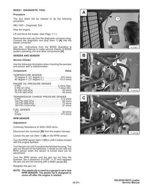
- Page 406 and 407: SERVICE CODES (Cont’d) The follow
- Page 408 and 409: TROUBLESHOOTING THE BOSS® & LCD DI
- Page 410 and 411: BOSS® INSTRUMENT PANEL Removal and
- Page 412 and 413: PWM MODULE (Cont’d) Description (
- Page 414 and 415: PWM CONTROL HANDLE Handle Testing T
- Page 416 and 417: SPECIFICATIONS Page Number DECIMAL
- Page 418 and 419: LOADER SPECIFICATIONS LOADER DIMENS
- Page 420 and 421: ENGINE SPECIFICATIONS All dimension
- Page 422 and 423: ENGINE SPECIFICATIONS (Cont’d) Al
- Page 424 and 425: TORQUE SPECIFICATIONS FOR LOADER Sp
- Page 426 and 427: HYDRAULIC/HYDROSTATIC FLUID SPECIFI
- Page 428 and 429: DECIMAL AND MILLIMETER EQUIVALENTS
- Page 430: AFFECTING: Product BOBCAT LOADER Mo
- Page 434: AFFECTING: Product BOBCAT LOADER Mo
- Page 437 and 438: TAKE OUT PUT IN 853 BICS - OPERATOR