

OMRON Sysdrive 3G3HV - Detector Cooling Section
OMRON Sysdrive 3G3HV - Detector Cooling Section
OMRON Sysdrive 3G3HV - Detector Cooling Section

Create successful ePaper yourself
Turn your PDF publications into a flip-book with our unique Google optimized e-Paper software.
Note 1. The up/down command is valid only if n002 (i.e., operation mode selection) is set to 1<br />
or 3.<br />
Note 2. The Inverter will accelerate or decelerate the motor according to the acceleration time<br />
or deceleration time set with n019 to n022 if the up/down command is input.<br />
Note 3. The following are the upper and lower limits of the output frequency when the Inverter<br />
accelerates or decelerates the motor with the up/down command.<br />
Upper limit: Maximum frequency (n012) x output frequency upper limit (n030)/100<br />
Lower limit: Maximum frequency (n012) x output frequency lower limit (n031)/100<br />
If an analog frequency reference is input through the FV or FI terminal and the value<br />
of the analog frequency reference is larger the above lower limit, the lower limit of the<br />
output frequency will be determined by the analog frequency reference.<br />
Note 4. The initial output frequency is 0.0 Hz if n039 is set to 25. The output frequency will<br />
reach the lower limit when the up/down command is input.<br />
Note 5. Turn ON input to S5 or S6 while the run command is OFF to set the frequency reference<br />
used by the Inverter to zero.<br />
Note 6. The multi-step speed command is invalid if n039 is set to 25.<br />
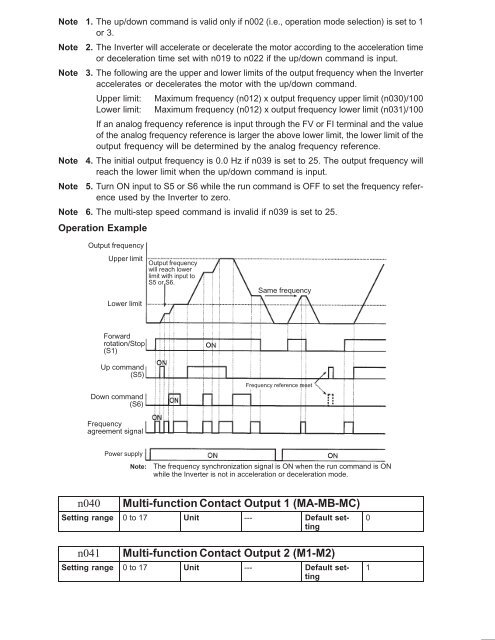
Operation Example<br />
Output frequency<br />
Upper limit<br />
Lower limit<br />
Output frequency<br />
will reach lower<br />
limit with input to<br />
S5 or S6.<br />
Same frequency<br />
Forward<br />
rotation/Stop<br />
(S1)<br />
Up command<br />
(S5)<br />
Down command<br />
(S6)<br />
Frequency reference reset<br />
Frequency<br />
agreement signal<br />
Power supply<br />
Note:<br />
The frequency synchronization signal is ON when the run command is ON<br />
while the Inverter is not in acceleration or deceleration mode.<br />
n040<br />
Multi-function Contact Output 1 (MA-MB-MC)<br />
Setting range 0 to 17 Unit --- Default setting<br />
n041<br />
Multi-function Contact Output 2 (M1-M2)<br />
Setting range 0 to 17 Unit --- Default setting<br />
0<br />
1


