

OMRON Sysdrive 3G3HV - Detector Cooling Section
OMRON Sysdrive 3G3HV - Detector Cooling Section
OMRON Sysdrive 3G3HV - Detector Cooling Section

You also want an ePaper? Increase the reach of your titles
YUMPU automatically turns print PDFs into web optimized ePapers that Google loves.
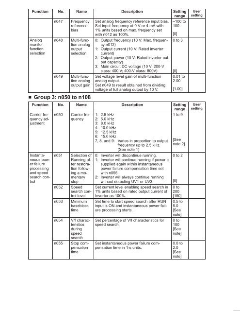
Function<br />
Analog<br />
monitor<br />
function<br />
selection<br />
No.<br />
n047<br />
n048<br />
n049<br />
Name<br />
Frequency<br />
reference<br />
bias<br />
Multi-function<br />
analog<br />
output<br />
selection<br />
Multi-function<br />
analog<br />
output gain<br />
Group 3: n050 to n108<br />
Description<br />
Set analog frequency reference input bias.<br />
Set input frequency at 0 V or 4 mA with<br />
1% units based on max. frequency set<br />
with n012 as 100%.<br />
0: Output frequency (10 V: Max. frequency<br />
n012)<br />
1: Output current (10 V: Rated inverter<br />
current)<br />
2: Output power (10 V: Rated inverter output<br />
capacity)<br />
3: Main circuit DC voltage (10 V: 200-V<br />
class: 400 V; 400-V class: 800V)<br />
Set voltage level gain of multi-function<br />
analog output.<br />
Set n049 to result obtained from dividing<br />
voltage of full analog output by 10 V.<br />
Setting<br />
range<br />
–100 to<br />
100<br />
[0]<br />
0 to 3<br />
[0]<br />
0.01 to<br />
2.00<br />
[1.00]<br />
Function No. Name Description Setting<br />
range<br />
Carrier frequency<br />
adjustment<br />
Carrier frequency<br />
Instantaneous<br />
power<br />
failure<br />
processing<br />
and speed<br />
search con-<br />
trol<br />
n050<br />
n051<br />
n052<br />
n053<br />
n054<br />
n055<br />
Selection of<br />
Running after<br />
restoration<br />
following<br />
a momentary<br />
stop<br />
Speed<br />
search control<br />
level<br />
Minimum<br />
baseblock<br />
time<br />
V/f characteristics<br />
during<br />
speed<br />
search<br />
Stop compensation<br />
time<br />
1: 2.5 kHz<br />
2: 5.0 kHz<br />
3: 8.0 kHz<br />
4: 10.0 kHz<br />
5: 12.5 kHz<br />
6: 15.0 kHz<br />
7, 8, and 9: Varies in proportion to output<br />
frequency up to 2.5 kHz.<br />
(See note 1)<br />
0: Inverter will discontinue running.<br />
1: Inverter will continue running if power is<br />
supplied again within instantaneous<br />
power failure compensation time set<br />
with n055.<br />
2: Inverter will always continue running<br />
without detecting UV1 or UV3.<br />
Set current level enabling speed search in<br />
1% units based on rated output current of<br />
Inverter as 100%.<br />
Set time to start speed search after RUN<br />
input is ON and instantaneous power failure<br />
processing starts.<br />
Set percentage of V/f characteristics for<br />
speed search.<br />
Set instantaneous power failure compensation<br />
time in 1-s units.<br />
1 to 9<br />
[See<br />
note 2]<br />
0 to 2<br />
[0]<br />
0 to<br />
200<br />
[150]<br />
0.5 to<br />
5.0<br />
[See<br />
note]<br />
0 to<br />
100<br />
[See<br />
note]<br />
0.0 to<br />
2.0<br />
[See<br />
note]<br />
User<br />
setting<br />
User<br />
setting


