

OMRON Sysdrive 3G3HV - Detector Cooling Section
OMRON Sysdrive 3G3HV - Detector Cooling Section
OMRON Sysdrive 3G3HV - Detector Cooling Section

Create successful ePaper yourself
Turn your PDF publications into a flip-book with our unique Google optimized e-Paper software.
Note<br />
Note<br />
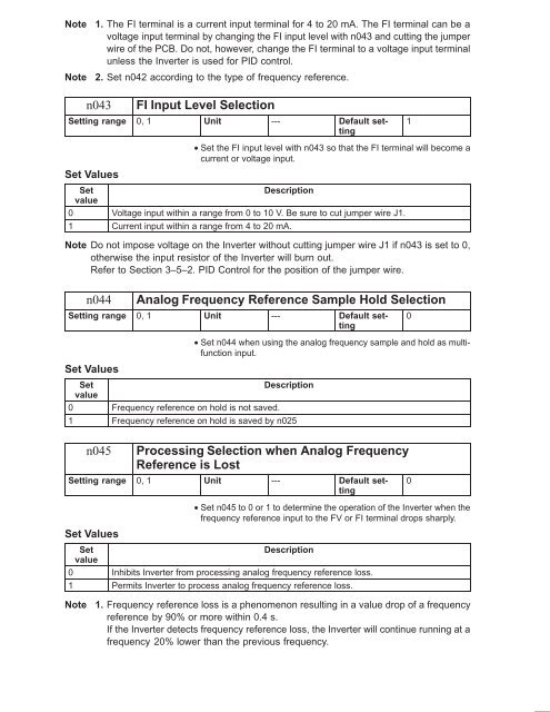
1. The FI terminal is a current input terminal for 4 to 20 mA. The FI terminal can be a<br />
voltage input terminal by changing the FI input level with n043 and cutting the jumper<br />
wire of the PCB. Do not, however, change the FI terminal to a voltage input terminal<br />
unless the Inverter is used for PID control.<br />
2. Set n042 according to the type of frequency reference.<br />
n043<br />
FI Input Level Selection<br />
Setting range 0, 1 Unit --- Default setting<br />
1<br />
• Set the FI input level with n043 so that the FI terminal will become a<br />
current or voltage input.<br />
Set Values<br />
Set<br />
Description<br />
value<br />
0 Voltage input within a range from 0 to 10 V. Be sure to cut jumper wire J1.<br />
1 Current input within a range from 4 to 20 mA.<br />
Note Do not impose voltage on the Inverter without cutting jumper wire J1 if n043 is set to 0,<br />
otherwise the input resistor of the Inverter will burn out.<br />
Refer to <strong>Section</strong> 3–5–2. PID Control for the position of the jumper wire.<br />
n044<br />
Analog Frequency Reference Sample Hold Selection<br />
Setting range 0, 1 Unit --- Default setting<br />
Set Values<br />
Set<br />
Description<br />
value<br />
0 Frequency reference on hold is not saved.<br />
1 Frequency reference on hold is saved by n025<br />
• Set n044 when using the analog frequency sample and hold as multifunction<br />
input.<br />
0<br />
n045<br />
Processing Selection when Analog Frequency<br />
Reference is Lost<br />
Setting range 0, 1 Unit --- Default setting<br />
Set Values<br />
• Set n045 to 0 or 1 to determine the operation of the Inverter when the<br />
frequency reference input to the FV or FI terminal drops sharply.<br />
Set<br />
Description<br />
value<br />
0 Inhibits Inverter from processing analog frequency reference loss.<br />
1 Permits Inverter to process analog frequency reference loss.<br />
0<br />
Note<br />
1. Frequency reference loss is a phenomenon resulting in a value drop of a frequency<br />
reference by 90% or more within 0.4 s.<br />
If the Inverter detects frequency reference loss, the Inverter will continue running at a<br />
frequency 20% lower than the previous frequency.


