- Page 1 and 2: Function The 3G3HV High-capacity Ge
- Page 3 and 4: • Two acceleration times and two
- Page 5 and 6: Digital Operator Easy-setting indic
- Page 7 and 8: 3G3HV-A2110/-A2150/-A4110/-A4150 E
- Page 9 and 10: 3G3HV-B2750/-B411K/-B416K External
- Page 11 and 12: Installation Conditions Cautions a
- Page 13 and 14: Wiring Cautions and Warnings ! WAR
- Page 15 and 16: • Do not mount the front cover wi
- Page 17 and 18: 400-V Class Model 3G3HV- A4037 to A
- Page 19 and 20: Standard Connection Diagram For In
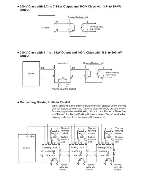
- Page 21 and 22: Wiring Around the Main Circuit Syst
- Page 23 and 24: Voltage class Model Terminal Termin
- Page 25 and 26: Round Solderless Terminals and Tigh
- Page 27 and 28: peak current may flow through the i
- Page 29 and 30: inrush current will actuate the ove
- Page 31 and 32: • When using more than one Invert
- Page 33 and 34: atio of harmonics in the output cur
- Page 35: Do not ground the secondary winding
- Page 39 and 40: Preparation Procedure Installation
- Page 41 and 42: Nomenclature Easy-setting indicator
- Page 43 and 44: Indicator Item Function Fref Speed
- Page 45 and 46: Monitor Monitor item No. U-01 Frequ
- Page 47 and 48: Check the rated input voltage of th
- Page 49 and 50: Change the frequency reference and
- Page 51 and 52: Set Values Set value Run command Fr
- Page 53 and 54: n027 Frequency Reference 3 Setting
- Page 55 and 56: n039 Multi-function Input 5 (S6) Se
- Page 57 and 58: Select one of the 15 V/f patterns p
- Page 59 and 60: n012 Maximum Frequency (FMAX) Setti
- Page 61 and 62: Energy-saving Mode The Inverter in
- Page 63 and 64: Note speed motors (e.g., spindle mo
- Page 65 and 66: does not save unnecessary power sup
- Page 67 and 68: PID Control PID (proportional, inte
- Page 69 and 70: PID Control Function Refer to the f
- Page 71 and 72: Set Values • The parameters n086,
- Page 73 and 74: PID Parameters The following can be
- Page 75 and 76: Suppression of Short-cycle Vibratio
- Page 77 and 78: Function No. Name Description Setti
- Page 79 and 80: Function No. Name Description Setti
- Page 81 and 82: Group 2: n035 to n049 Function No.
- Page 83 and 84: Function Analog monitor function se
- Page 85 and 86: Function No. Name Description Setti
- Page 87 and 88:
Function I/O phase loss detection N
- Page 89 and 90:
Function No. Name Description Setti
- Page 91 and 92:
Note 1. Do not set n001 to any valu
- Page 93 and 94:
Set Values Set value 0 The motor ca
- Page 95 and 96:
Characteristics of V/f Patterns Ge
- Page 97 and 98:
Note The V/f pattern will be a stra
- Page 99 and 100:
n029 Setting range Inching Frequenc
- Page 101 and 102:
Set Values Set Description value 0
- Page 103 and 104:
2-wire Sequence (n035 = 0) Wiring E
- Page 105 and 106:
Acceleration/Deceleration Time Swit
- Page 107 and 108:
Inverter Overheat Warning (Set Valu
- Page 109 and 110:
• The functions of multi-function
- Page 111 and 112:
Optional Frequency Detection: Outpu
- Page 113 and 114:
Note 2. To permit the Inverter to o
- Page 115 and 116:
n Carrier 0frequency (fc) 5 2.5 kHz
- Page 117 and 118:
When the Inverter is in normal oper
- Page 119 and 120:
n066 • Set with n065 DC control t
- Page 121 and 122:
• Set with n071 and n072 current
- Page 123 and 124:
Set Values Set Description value 0
- Page 125 and 126:
Protective and Diagnostic Functions
- Page 127 and 128:
Data display rh rr Description Brak
- Page 129 and 130:
Data display %h3 flashing %l3 flash
- Page 131 and 132:
verter if n002 is set to 0 or 2 or
- Page 133 and 134:
Controller Receives Noise When Inve
- Page 135 and 136:
Maintenance and Inspection Caution
- Page 137 and 138:
Specifications of Inverters General
- Page 139 and 140:
Control Characteristics Model 3G3HV
- Page 141 and 142:
3G3HV-PCMA2 Voltage/Current Convers
- Page 143 and 144:
External Dimensions 75 min. 120 min
- Page 145 and 146:
3G3IV-PJVOP95 Analog Operator (Mini
- Page 147 and 148:
3G3IV-PLKEB Braking Resistor Unit T
- Page 149 and 150:
3G3IV-PUZBAB A MH AC Reactor Connec
- Page 151 and 152:
Dimensions A B B1 C D E F H J K L M
- Page 153 and 154:
External Dimensions Model 3G3IV- Ap
- Page 155 and 156:
3G3IV-PLF Output Noise Filter (Toki
- Page 157 and 158:
Notes on Using the Inverter for a M
- Page 159 and 160:
Motor Burnout Due to Insufficient D
- Page 161 and 162:
Voltage Enclosure rating Max. motor
- Page 163 and 164:
Function No. Name Description Setti
- Page 165 and 166:
Function No. Name Description Setti
- Page 167 and 168:
Group 2: n035 to n049 Function No.
- Page 169 and 170:
Function Analog monitor function se
- Page 171 and 172:
Function No. Name Description Setti
- Page 173 and 174:
Function No. Name Description Setti
- Page 175 and 176:
Function No. n095 n096 n097 n098 n0


