

OMRON Sysdrive 3G3HV - Detector Cooling Section
OMRON Sysdrive 3G3HV - Detector Cooling Section
OMRON Sysdrive 3G3HV - Detector Cooling Section

You also want an ePaper? Increase the reach of your titles
YUMPU automatically turns print PDFs into web optimized ePapers that Google loves.
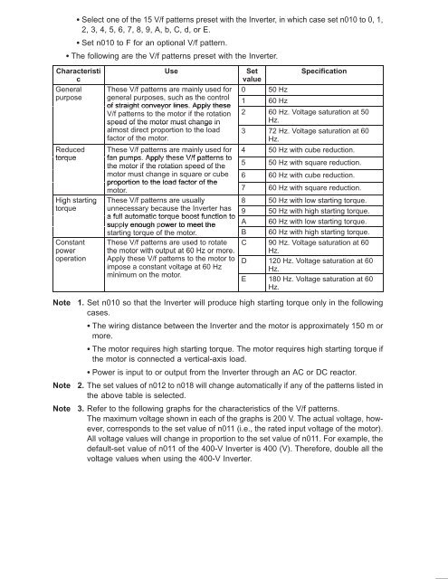
Select one of the 15 V/f patterns preset with the Inverter, in which case set n010 to 0, 1,<br />
2, 3, 4, 5, 6, 7, 8, 9, A, b, C, d, or E.<br />
Set n010 to F for an optional V/f pattern.<br />
The following are the V/f patterns preset with the Inverter.<br />
Characteristi<br />
c<br />
General<br />
purpose<br />
Reduced<br />
torque<br />
High starting<br />
torque<br />
Constant<br />
power<br />
operation<br />
Use<br />
Set<br />
value<br />
Specification<br />
These V/f patterns are mainly used for 0 50 Hz<br />
general purposes, such as the control<br />
1 60 Hz<br />
of straight conveyor lines. Apply these<br />
V/f patterns to the motor if the rotation 2 60 Hz. Voltage saturation at 50<br />
speed of the motor must change in<br />
Hz.<br />
almost direct proportion to the load 3 72 Hz. Voltage saturation at 60<br />
factor of the motor.<br />
Hz.<br />
These V/f patterns are mainly used for 4 50 Hz with cube reduction.<br />
fan pumps. Apply these V/f patterns to<br />
the motor if the rotation speed of the<br />
5 50 Hz with square reduction.<br />
motor must change in square or cube 6 60 Hz with cube reduction.<br />
proportion to the load factor of the<br />
motor. 7 60 Hz with square reduction.<br />
These V/f patterns are usually<br />
8 50 Hz with low starting torque.<br />
unnecessary because the Inverter has 9 50 Hz with high starting torque.<br />
a full automatic torque boost function to<br />
supply enough power to meet the<br />
A 60 Hz with low starting torque.<br />
starting torque of the motor. B 60 Hz with high starting torque.<br />
These V/f patterns are used to rotate C 90 Hz. Voltage saturation at 60<br />
the motor with output at 60 Hz or more. Hz.<br />
Apply these V/f patterns to the motor to D 120 Hz. Voltage saturation at 60<br />
impose a constant voltage at 60 Hz<br />
Hz.<br />
minimum on the motor.<br />
E 180 Hz. Voltage saturation at 60<br />
Hz.<br />
Note<br />
Note<br />
Note<br />
1. Set n010 so that the Inverter will produce high starting torque only in the following<br />
cases.<br />
The wiring distance between the Inverter and the motor is approximately 150 m or<br />
more.<br />
The motor requires high starting torque. The motor requires high starting torque if<br />
the motor is connected a vertical-axis load.<br />
Power is input to or output from the Inverter through an AC or DC reactor.<br />
2. The set values of n012 to n018 will change automatically if any of the patterns listed in<br />
the above table is selected.<br />
3. Refer to the following graphs for the characteristics of the V/f patterns.<br />
The maximum voltage shown in each of the graphs is 200 V. The actual voltage, however,<br />
corresponds to the set value of n011 (i.e., the rated input voltage of the motor).<br />
All voltage values will change in proportion to the set value of n011. For example, the<br />
default-set value of n011 of the 400-V Inverter is 400 (V). Therefore, double all the<br />
voltage values when using the 400-V Inverter.


