

OMRON Sysdrive 3G3HV - Detector Cooling Section
OMRON Sysdrive 3G3HV - Detector Cooling Section
OMRON Sysdrive 3G3HV - Detector Cooling Section

Create successful ePaper yourself
Turn your PDF publications into a flip-book with our unique Google optimized e-Paper software.
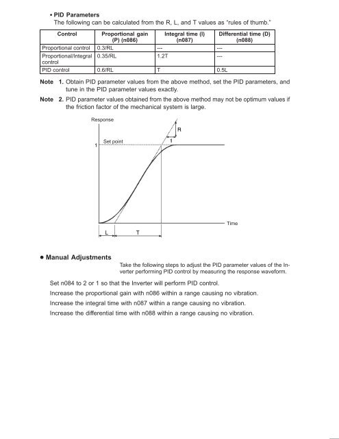
PID Parameters<br />
The following can be calculated from the R, L, and T values as “rules of thumb.”<br />
Control<br />
Proportional gain<br />
(P) (n086)<br />
Integral time (I)<br />
(n087)<br />
Proportional control 0.3/RL --- ---<br />
Proportional/Integral 0.35/RL 1.2T ---<br />
control<br />
PID control 0.6/RL T 0.5L<br />
Differential time (D)<br />
(n088)<br />
Note<br />
Note<br />
1. Obtain PID parameter values from the above method, set the PID parameters, and<br />
tune in the PID parameter values exactly.<br />
2. PID parameter values obtained from the above method may not be optimum values if<br />
the friction factor of the mechanical system is large.<br />
Response<br />
Set point<br />
Time<br />
Manual Adjustments<br />
Take the following steps to adjust the PID parameter values of the Inverter<br />
performing PID control by measuring the response waveform.<br />
Set n084 to 2 or 1 so that the Inverter will perform PID control.<br />
Increase the proportional gain with n086 within a range causing no vibration.<br />
Increase the integral time with n087 within a range causing no vibration.<br />
Increase the differential time with n088 within a range causing no vibration.


