

OMRON Sysdrive 3G3HV - Detector Cooling Section
OMRON Sysdrive 3G3HV - Detector Cooling Section
OMRON Sysdrive 3G3HV - Detector Cooling Section

Create successful ePaper yourself
Turn your PDF publications into a flip-book with our unique Google optimized e-Paper software.
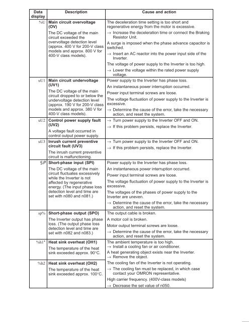
Data<br />
Description<br />
display<br />
%U Main circuit overvoltage<br />
(OV)<br />
The DC voltage of the main<br />
circuit exceeded the<br />
overvoltage detection level<br />
(approx. 400 V for 200-V class<br />
models and approx. 800 V for<br />
400-V class models).<br />
uU1<br />
uU2<br />
uU3<br />
sp%<br />
%h1*<br />
Main circuit undervoltage<br />
(UV1)<br />
The DC voltage of the main<br />
circuit dropped to or below the<br />
undervoltage detection level<br />
(approx. 190 V for 200-V class<br />
models and approx. 380 V for<br />
400-V class models).<br />
Control power supply fault<br />
(UV2)<br />
A voltage fault occurred in<br />
control output power supply.<br />
Inrush current preventive<br />
circuit fault (UV3)<br />
The inrush current preventive<br />
circuit is malfunctioning.<br />
Short-phase input (SPI)<br />
The DC voltage of the main<br />
circuit fluctuates excessively<br />
while the Inverter is not<br />
affected by regenerative<br />
energy. (The input phase loss<br />
detection level and time are<br />
set with n080 and n081.)<br />
Short-phase output (SPO)<br />
The Inverter output has phase<br />
loss. (The output phase loss<br />
detection level and time are<br />
set with n082 and n083.)<br />
Heat sink overheat (OH1)<br />
The temperature of the heat<br />
sink exceeded approx. 90°C.<br />
%h2 Heat sink overheat (OH2)<br />
The temperature of the heat<br />
sink exceeded approx. 100°C.<br />
Cause and action<br />
The deceleration time setting is too short and<br />
regenerative energy from the motor is excessive.<br />
→ Increase the deceleration time or connect the Braking<br />
Resistor Unit.<br />
A surge is imposed when the phase advance capacitor is<br />
switched.<br />
→ Insert an AC reactor into the power input side of the<br />
Inverter.<br />
The voltage of power supply to the Inverter is too high.<br />
→ Lower the voltage within the rated power supply<br />
voltage.<br />
Power supply to the Inverter has phase loss.<br />
An instantaneous power interruption occurred.<br />
Power input terminal screws are loose.<br />
The voltage fluctuation of power supply to the Inverter is<br />
excessive.<br />
→ Determine the cause of the error, take the necessary<br />
action, and reset the system.<br />
→ Turn power supply to the Inverter OFF and ON.<br />
→ If this problem persists, replace the Inverter.<br />
→ Turn power supply to the Inverter OFF and ON.<br />
→ If this problem persists, replace the Inverter.<br />
Power supply to the Inverter has phase loss.<br />
An instantaneous power interruption occurred.<br />
Power input terminal screws are loose.<br />
The voltage fluctuation of power supply to the Inverter is<br />
excessive.<br />
The voltages of the phases of power supply to the<br />
Inverter are uneven.<br />
→ Determine the cause of the error, take the necessary<br />
action, and reset the system.<br />
The output cable is broken.<br />
A motor coil is broken.<br />
Motor output terminal screws are loose.<br />
→ Determine the cause of the error, take the necessary<br />
action, and reset the system.<br />
The ambient temperature is too high.<br />
→ Install a cooling fan or air conditioner.<br />
A heat generating object exists near the Inverter.<br />
→ Remove the object.<br />
The cooling fan of the Inverter is not operating.<br />
→ The cooling fan must be replaced, in which case<br />
contact your <strong>OMRON</strong> representative.<br />
High carrier frequency. (400V-class models)<br />
→ Decrease the set value of n050.


