

OMRON Sysdrive 3G3HV - Detector Cooling Section
OMRON Sysdrive 3G3HV - Detector Cooling Section
OMRON Sysdrive 3G3HV - Detector Cooling Section

You also want an ePaper? Increase the reach of your titles
YUMPU automatically turns print PDFs into web optimized ePapers that Google loves.
n043<br />
FI Input Level Selection<br />
Setting range 0, 1 Unit --- Default setting<br />
1<br />
Set Values<br />
Set<br />
Description<br />
value<br />
0 Voltage input within a range from 0 to 10 V. Be sure to cut jumper wire J1.<br />
1 Current input within a range from 4 to 20 mA.<br />
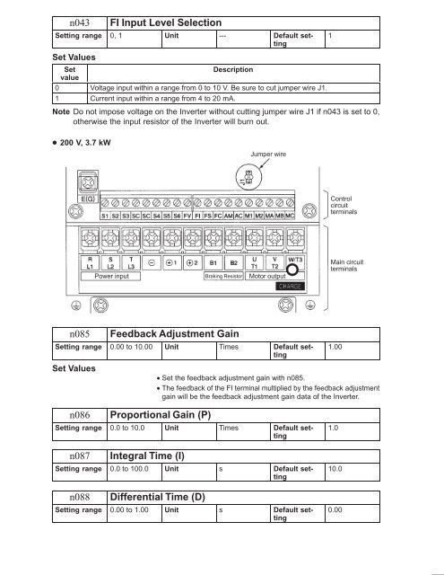
Note Do not impose voltage on the Inverter without cutting jumper wire J1 if n043 is set to 0,<br />
otherwise the input resistor of the Inverter will burn out.<br />
200 V, 3.7 kW<br />
Jumper wire<br />
Control<br />
circuit<br />
terminals<br />
Power input Braking Resistor Motor output<br />
Main circuit<br />
terminals<br />
n085<br />
Feedback Adjustment Gain<br />
Setting range 0.00 to 10.00 Unit Times Default setting<br />
1.00<br />
Set Values<br />
• Set the feedback adjustment gain with n085.<br />
• The feedback of the FI terminal multiplied by the feedback adjustment<br />
gain will be the feedback adjustment gain data of the Inverter.<br />
n086<br />
Proportional Gain (P)<br />
Setting range 0.0 to 10.0 Unit Times Default setting<br />
n087<br />
Integral Time (I)<br />
Setting range 0.0 to 100.0 Unit s Default setting<br />
n088<br />
Differential Time (D)<br />
Setting range 0.00 to 1.00 Unit s Default setting<br />
1.0<br />
10.0<br />
0.00


