

OMRON Sysdrive 3G3HV - Detector Cooling Section
OMRON Sysdrive 3G3HV - Detector Cooling Section
OMRON Sysdrive 3G3HV - Detector Cooling Section

You also want an ePaper? Increase the reach of your titles
YUMPU automatically turns print PDFs into web optimized ePapers that Google loves.
• By setting n092 to 1, the Inverter determines that the feedback line is<br />
disconnected if the Inverter receives a feedback value that is too low.<br />
• The Inverter will have PID feedback loss output as multi-function output<br />
if the Inverter detects feedback loss. Therefore, program a sequence<br />
to interrupt the operation of the Inverter.<br />
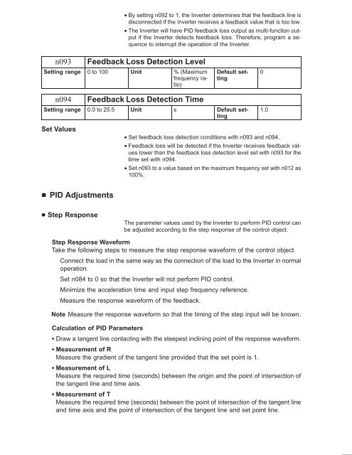
n093<br />
Feedback Loss Detection Level<br />
Setting range 0 to 100 Unit % (Maximum<br />
frequency ratio)<br />
Default setting<br />
0<br />
n094<br />
Feedback Loss Detection Time<br />
Setting range 0.0 to 25.5 Unit s Default setting<br />
1.0<br />
Set Values<br />
• Set feedback loss detection conditions with n093 and n094.<br />
• Feedback loss will be detected if the Inverter receives feedback values<br />
lower than the feedback loss detection level set with n093 for the<br />
time set with n094.<br />
• Set n093 to a value based on the maximum frequency set with n012 as<br />
100%.<br />
PID Adjustments<br />
Step Response<br />
The parameter values used by the Inverter to perform PID control can<br />
be adjusted according to the step response of the control object.<br />
Step Response Waveform<br />
Take the following steps to measure the step response waveform of the control object.<br />
Connect the load in the same way as the connection of the load to the Inverter in normal<br />
operation.<br />
Set n084 to 0 so that the Inverter will not perform PID control.<br />
Minimize the acceleration time and input step frequency reference.<br />
Measure the response waveform of the feedback.<br />
Note Measure the response waveform so that the timing of the step input will be known.<br />
Calculation of PID Parameters<br />
Draw a tangent line contacting with the steepest inclining point of the response waveform.<br />
Measurement of R<br />
Measure the gradient of the tangent line provided that the set point is 1.<br />
Measurement of L<br />
Measure the required time (seconds) between the origin and the point of intersection of<br />
the tangent line and time axis.<br />
Measurement of T<br />
Measure the required time (seconds) between the point of intersection of the tangent line<br />
and time axis and the point of intersection of the tangent line and set point line.


