

OMRON Sysdrive 3G3HV - Detector Cooling Section
OMRON Sysdrive 3G3HV - Detector Cooling Section
OMRON Sysdrive 3G3HV - Detector Cooling Section

You also want an ePaper? Increase the reach of your titles
YUMPU automatically turns print PDFs into web optimized ePapers that Google loves.
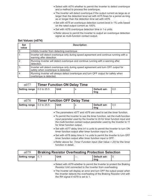
• Select with n074 whether to permit the Inverter to detect overtorque<br />
and a method to process the overtorque.<br />
• The Inverter will detect overtorque if the output current as large as or<br />
larger than the detection level set with n075 flows for a period as long<br />
as or longer than the detection time set with n076.<br />
• Set with n075 an overtorque detection current level in 1% units based<br />
on the rated output current as 100%.<br />
• Set with n076 overtorque detection time in 1-s units.<br />
• Refer above to permit the Inverter to output an overtorque detection<br />
signal as multi-function contact output.<br />
Set Values (n074)<br />
Set<br />
Description<br />
value<br />
0 Inhibits Inverter from detecting overtorque.<br />
1 Inverter will detect overtorque only during speed agreement and continue running with a<br />
warning after detection.<br />
2 Running Inverter will detect overtorque and continue running with a warning after<br />
detection.<br />
3 Inverter will detect overtorque only during speed agreement and turn OFF output for<br />
safety when overtorque is detected.<br />
4 Running Inverter will always detect overtorque and turn OFF output for safety when<br />
overtorque is detected.<br />
n077<br />
Timer Function ON Delay Time<br />
Setting range 0.0 to 25.5 Unit s Default setting<br />
0.0<br />
n078<br />
Timer Function OFF Delay Time<br />
Setting range 0.0 to 25.5 Unit s Default setting<br />
0.0<br />
• The parameters n077 and n078 are used to set the timer function.<br />
• To permit the Inverter to use the timer function, set the multi-function<br />
input parameter used by the Inverter to 20 for timer function input and<br />
the multi-function contact output parameter used by the Inverter to 11<br />
for timer function output.<br />
• Set with n077 delay time in1-s units to permit the Inverter to turn ON<br />
timer function output after timer function input is ON.<br />
• Set with n078 delay time in 1-s units to permit the Inverter to turn OFF<br />
timer function output after timer function input is OFF.<br />
• Refer above for, Timer Function Input (Set Value = 20) for the timer<br />
function in detail.<br />
n079<br />
Braking Resistor Overheating Protection Selection<br />
Setting range 0, 1 Unit --- Default setting<br />
• Select with n079 whether to permit the Inverter to protect the Braking<br />
Resistor Unit connected to the Inverter from overheating.<br />
• The Inverter will display an error and turn OFF the output power when<br />
the Inverter detects the overheating of the Braking Resistor Unit with<br />
the RH signal if n079 is set to 1.<br />
0


