

OMRON Sysdrive 3G3HV - Detector Cooling Section
OMRON Sysdrive 3G3HV - Detector Cooling Section
OMRON Sysdrive 3G3HV - Detector Cooling Section

Create successful ePaper yourself
Turn your PDF publications into a flip-book with our unique Google optimized e-Paper software.
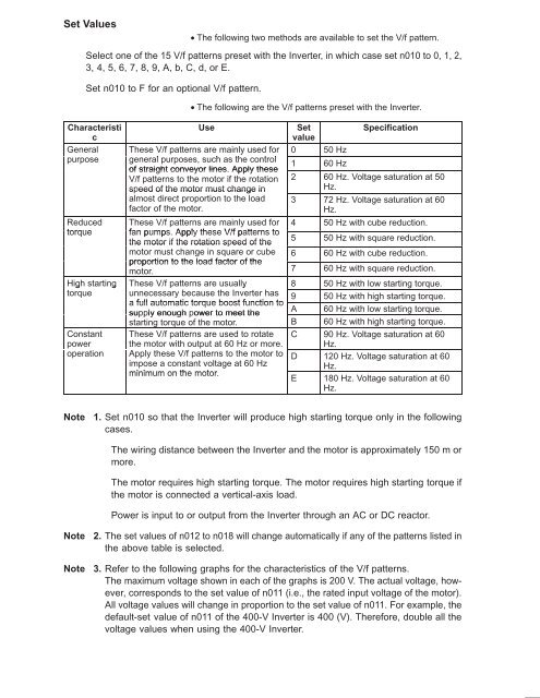
Set Values<br />
• The following two methods are available to set the V/f pattern.<br />
Select one of the 15 V/f patterns preset with the Inverter, in which case set n010 to 0, 1, 2,<br />
3, 4, 5, 6, 7, 8, 9, A, b, C, d, or E.<br />
Set n010 to F for an optional V/f pattern.<br />
• The following are the V/f patterns preset with the Inverter.<br />
Characteristi<br />
c<br />
General<br />
purpose<br />
Reduced<br />
torque<br />
High starting<br />
torque<br />
Constant<br />
power<br />
operation<br />
Use<br />
Set<br />
value<br />
Specification<br />
These V/f patterns are mainly used for 0 50 Hz<br />
general purposes, such as the control<br />
1 60 Hz<br />
of straight conveyor lines. Apply these<br />
V/f patterns to the motor if the rotation 2 60 Hz. Voltage saturation at 50<br />
speed of the motor must change in<br />
Hz.<br />
almost direct proportion to the load 3 72 Hz. Voltage saturation at 60<br />
factor of the motor.<br />
Hz.<br />
These V/f patterns are mainly used for 4 50 Hz with cube reduction.<br />
fan pumps. Apply these V/f patterns to<br />
the motor if the rotation speed of the<br />
5 50 Hz with square reduction.<br />
motor must change in square or cube 6 60 Hz with cube reduction.<br />
proportion to the load factor of the<br />
motor. 7 60 Hz with square reduction.<br />
These V/f patterns are usually<br />
8 50 Hz with low starting torque.<br />
unnecessary because the Inverter has 9 50 Hz with high starting torque.<br />
a full automatic torque boost function to<br />
supply enough power to meet the<br />
A 60 Hz with low starting torque.<br />
starting torque of the motor. B 60 Hz with high starting torque.<br />
These V/f patterns are used to rotate C 90 Hz. Voltage saturation at 60<br />
the motor with output at 60 Hz or more. Hz.<br />
Apply these V/f patterns to the motor to D 120 Hz. Voltage saturation at 60<br />
impose a constant voltage at 60 Hz<br />
Hz.<br />
minimum on the motor.<br />
E 180 Hz. Voltage saturation at 60<br />
Hz.<br />
Note<br />
1. Set n010 so that the Inverter will produce high starting torque only in the following<br />
cases.<br />
The wiring distance between the Inverter and the motor is approximately 150 m or<br />
more.<br />
The motor requires high starting torque. The motor requires high starting torque if<br />
the motor is connected a vertical-axis load.<br />
Power is input to or output from the Inverter through an AC or DC reactor.<br />
Note<br />
Note<br />
2. The set values of n012 to n018 will change automatically if any of the patterns listed in<br />
the above table is selected.<br />
3. Refer to the following graphs for the characteristics of the V/f patterns.<br />
The maximum voltage shown in each of the graphs is 200 V. The actual voltage, however,<br />
corresponds to the set value of n011 (i.e., the rated input voltage of the motor).<br />
All voltage values will change in proportion to the set value of n011. For example, the<br />
default-set value of n011 of the 400-V Inverter is 400 (V). Therefore, double all the<br />
voltage values when using the 400-V Inverter.


