

OMRON Sysdrive 3G3HV - Detector Cooling Section
OMRON Sysdrive 3G3HV - Detector Cooling Section
OMRON Sysdrive 3G3HV - Detector Cooling Section

You also want an ePaper? Increase the reach of your titles
YUMPU automatically turns print PDFs into web optimized ePapers that Google loves.
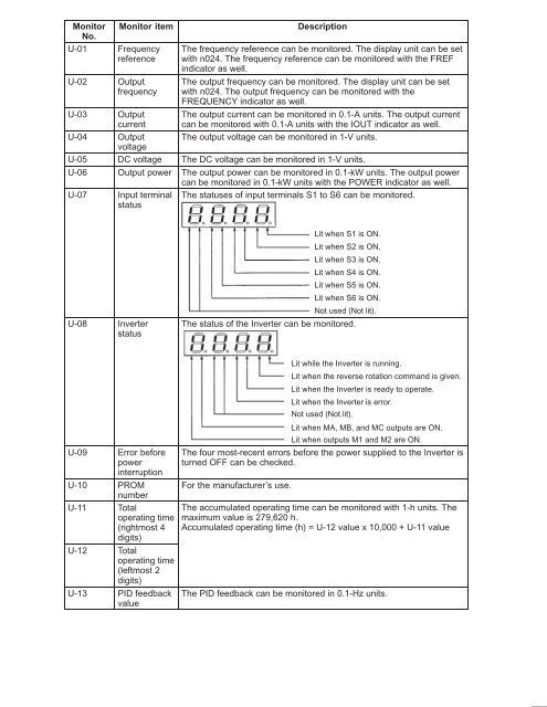
Monitor Monitor item<br />
No.<br />
U-01 Frequency<br />
reference<br />
U-02 Output<br />
frequency<br />
U-03 Output<br />
current<br />
U-04 Output<br />
voltage<br />
Description<br />
The frequency reference can be monitored. The display unit can be set<br />
with n024. The frequency reference can be monitored with the FREF<br />
indicator as well.<br />
The output frequency can be monitored. The display unit can be set<br />
with n024. The output frequency can be monitored with the<br />
FREQUENCY indicator as well.<br />
The output current can be monitored in 0.1-A units. The output current<br />
can be monitored with 0.1-A units with the IOUT indicator as well.<br />
The output voltage can be monitored in 1-V units.<br />
U-05 DC voltage The DC voltage can be monitored in 1-V units.<br />
U-06 Output power The output power can be monitored in 0.1-kW units. The output power<br />
can be monitored in 0.1-kW units with the POWER indicator as well.<br />
U-07 Input terminal<br />
status<br />
The statuses of input terminals S1 to S6 can be monitored.<br />
Lit when S1 is ON.<br />
Lit when S2 is ON.<br />
Lit when S3 is ON.<br />
Lit when S4 is ON.<br />
Lit when S5 is ON.<br />
Lit when S6 is ON.<br />
U-08 Inverter<br />
status<br />
Not used (Not lit).<br />
The status of the Inverter can be monitored.<br />
U-09 Error before<br />
power<br />
interruption<br />
U-10 PROM<br />
number<br />
U-11 Total<br />
operating time<br />
(rightmost 4<br />
digits)<br />
U-12 Total<br />
operating time<br />
(leftmost 2<br />
digits)<br />
U-13 PID feedback<br />
value<br />
Lit while the Inverter is running.<br />
Lit when the reverse rotation command is given.<br />
Lit when the Inverter is ready to operate.<br />
Lit when the Inverter is error.<br />
Not used (Not lit).<br />
Lit when MA, MB, and MC outputs are ON.<br />
Lit when outputs M1 and M2 are ON.<br />
The four most-recent errors before the power supplied to the Inverter is<br />
turned OFF can be checked.<br />
For the manufacturer’s use.<br />
The accumulated operating time can be monitored with 1-h units. The<br />
maximum value is 279,620 h.<br />
Accumulated operating time (h) = U-12 value x 10,000 + U-11 value<br />
The PID feedback can be monitored in 0.1-Hz units.


