- Page 1 and 2: ~ National ~ Semiconductor 400014 R
- Page 3 and 4: TRADEMARKS Following is the most cu
- Page 5 and 6: II) c ~ ~National ~ ~ Semiconductor
- Page 7 and 8: Table of Contents (Continued) Secti
- Page 9 and 10: Alpha-Numeric Index(continUed) DS36
- Page 12 and 13: Section 1 Local Area Networks IEEE
- Page 14 and 15: ~National ~ Semiconductor DP8390C/N
- Page 16 and 17: 3.0 Functional Description (Continu
- Page 18 and 19: 5.0 Pin Descriptions (Continued) BU
- Page 20 and 21: 6.0 Direct Memory Access Control (D
- Page 24 and 25: 8.0 Packet Transmission (Continued)
- Page 26 and 27: 10.0 Internal Registers (Continued)
- Page 28 and 29: 10.0 Internal Registers (Continued)
- Page 30 and 31: 10.0 Internal Registers (Continued)
- Page 32 and 33: 10.0 Internal Registers (Continued)
- Page 34 and 35: 10.0 Internal Registers (Continued)
- Page 36 and 37: .----------------------------------
- Page 38 and 39: 10.0 Internal Registers (Continued)
- Page 40 and 41: 12.0 Loopback Diagnostics (Continue
- Page 42 and 43: 13.0 Bus Arbitration and Timing The
- Page 44 and 45: 13.0 Bus Arbitration and Timing (Co
- Page 46 and 47: 13.0 Bus Arbitration and Timing (Co
- Page 48 and 49: 15.0 Switching Characteristics AC S
- Page 50 and 51: 15.0 Switching Characteristics (Con
- Page 52 and 53: 15.0 Switching Characteristics (Con
- Page 54 and 55: 15.0 Switching Characteristics (Con
- Page 56 and 57: 15.0 Switching Characteristics (Con
- Page 58 and 59: 15.0 Switching Characteristics (Con
- Page 60 and 61: 15.0 Switching Characteristics (Con
- Page 62 and 63: 15.0 Switching Characteristics (Con
- Page 64 and 65: AC Timing Test Conditions Input Pul
- Page 66 and 67: 2.0 Block Diagram COL CRS PROTOCOL
- Page 68 and 69: 4.0 Transmit/Receive Packet Encapsu
- Page 70 and 71: 5.0 Pin Descriptions (Continued) BU
- Page 72 and 73:
7.0 Packet Reception (Continued) fo
- Page 74 and 75:
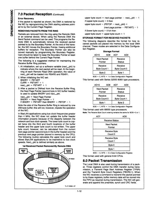
7.0 Packet Reception (Continued) Er
- Page 76 and 77:
9.0 Remote DMA The Remote DMA chann
- Page 78 and 79:
10.0 Internal Registers (Continued)
- Page 80 and 81:
10.0 Internal Registers (Continued)
- Page 82 and 83:
10.0 Internal Registers (Continued)
- Page 84 and 85:
10.0 Internal Registers (Continued)
- Page 86 and 87:
10.0 Internal Registers (Continued)
- Page 88 and 89:
10.0 Internal Registers (Continued)
- Page 90 and 91:
11.0 Initialization Procedures (Con
- Page 92 and 93:
13.0 Bus Arbitration and Timing The
- Page 94 and 95:
-----------------------------------
- Page 96 and 97:
13.0 Bus Arbitration and Timing (Co
- Page 98 and 99:
15.0 Switching Characteristics AC S
- Page 100 and 101:
15.0 Switching Characteristics (Con
- Page 102 and 103:
15.0 Switching Characteristics (Con
- Page 104 and 105:
15.0 Switching Characteristics (Con
- Page 106 and 107:
-----------------------------------
- Page 108 and 109:
15.0 Switching Characteristics (Con
- Page 110 and 111:
15.0 Switching Characteristics (Con
- Page 112 and 113:
15.0 Switching Characteristics (Con
- Page 114 and 115:
AC Timing Test Conditions Input Pul
- Page 116 and 117:
2.0 Block Diagram TRANSCEIVER CABLE
- Page 118 and 119:
PCC Connection Diagram 39.0. 39.0.
- Page 120 and 121:
6.0 Absolute Maximum Ratings Recomm
- Page 122 and 123:
9.0 Timing and Load Diagrams (Conti
- Page 124 and 125:
9.0 Timing and Load Diagrams (Conti
- Page 126 and 127:
2.0 Block Diagram COAX CABLE r ____
- Page 128 and 129:
~~L ~------------------------------
- Page 130 and 131:
6.0 Absolute Maximum Ratings (Note
- Page 132 and 133:
9.0 Timing and Load Diagrams (Conti
- Page 134 and 135:
-----------------------------------
- Page 136 and 137:
-----------------------------------
- Page 138 and 139:
I: • • • • • • Interrup
- Page 140 and 141:
PAL20LB Decode and DMA Interface Lo
- Page 142 and 143:
~ U16/8 R1 R1,R2=4.7k.o. Note: For
- Page 144 and 145:
Although Cheapernet is intended for
- Page 146 and 147:
The transmitted packet from the SNI
- Page 148 and 149:
Truth Table for Various Collision D
- Page 150 and 151:
CHEAPERNET APPLICATION WITH THE DP8
- Page 152 and 153:
DP8390 Network Interface Controller
- Page 154 and 155:
ping between the received address a
- Page 156 and 157:
If the current local DMA address ev
- Page 158 and 159:
6.2 Dual Port Memory One popular me
- Page 160 and 161:
StarLAN With The DP839EB Evaluation
- Page 162 and 163:
SUPPORTING DOCUMENTS The following
- Page 164 and 165:
Pulse Transformer U3 .----. j " "P>
- Page 166:
ELECTROSTATIC DISCHARGE TEST (ESD)
- Page 169 and 170:
Section 2 Contents DP8340INS32440 I
- Page 171 and 172:
.. 0 C'I C") en .... z 0 C") GO Go
- Page 173 and 174:
~ 'OIl' N CO) (J) Z .... o 'OIl' CO
- Page 175 and 176:
Timing Characteristics Oscillator F
- Page 177 and 178:
Timing Waveforms (Continued) TA REG
- Page 179 and 180:
.. ... ~ ~National ~ ~ Semiconduc
- Page 181 and 182:
Detailed Functional Pin Description
- Page 183 and 184:
Message Format (Continued) DATA REC
- Page 185 and 186:
Timing Characteristics (Notes 2, 6,
- Page 187 and 188:
Timing Waveforms (Continued) 4T±(T
- Page 189 and 190:
Typical Applications (Continued) +5
- Page 191 and 192:
N r--------------------------------
- Page 193 and 194:
~ ..,. r---------------------------
- Page 195 and 196:
Timing Characteristics (Continued)
- Page 197 and 198:
Functional Timing Waveforms (Contin
- Page 199 and 200:
Typical Applications (Continued) DA
- Page 201 and 202:
C") "Ot "Ot N C") en ...... z C") "
- Page 203 and 204:
) r--------------------------------
- Page 205 and 206:
Absolute Maximum Ratings (Note 1) I
- Page 207 and 208:
(W) r------------------------------
- Page 209 and 210:
M r--------------------------------
- Page 211 and 212:
MUX~ __________________ The BIPLAN
- Page 213 and 214:
U) ,-------------------------------
- Page 215 and 216:
~r---------------------------------
- Page 217 and 218:
~ .--------------------------------
- Page 219 and 220:
An EPROM implementation was selecte
- Page 221 and 222:
MASTER MUL TIPLEXING/DE-MUL TIPLEXI
- Page 223 and 224:
AN·496 '" 0, '" (U17/ (U23/6) TO 5
- Page 225 and 226:
AN-496 t W19 ~ J2-43 I' [; 0 J2-42
- Page 227 and 228:
AN·496
- Page 229 and 230:
DP8342/DP8343 HIGH SPEED INTERFACE
- Page 231 and 232:
2.0 Connection Diagram A13- 12 A12-
- Page 233 and 234:
3.0 Pin Descriptions (Continued) Si
- Page 235 and 236:
~ ~ 4.0 Electrical Specifications (
- Page 237 and 238:
4.0 Electrical Specifications (Cont
- Page 239 and 240:
~ ~ 4.0 Electrical Specifications (
- Page 241 and 242:
4.0 Electrical Specifications (Cont
- Page 243 and 244:
c( '
- Page 245 and 246:
~L ______________ ___ ~ ~ 4.0 Elect
- Page 247 and 248:
4.0 Electrical Specifications (Cont
- Page 249 and 250:
4.0 Electrical Specifications (Cont
- Page 251 and 252:
4.0 Electrical Specifications (Cont
- Page 253 and 254:
4.0 Electrical Specifications (Cont
- Page 255 and 256:
4.0 Electrical Specifications (Cont
- Page 257 and 258:
4.0 Electrical Specifications (Cont
- Page 259 and 260:
5.0 Instruction Set Overview (Conti
- Page 261 and 262:
5.0 Instruction Set Overview (Conti
- Page 263 and 264:
5.0 Instruction Set Overview (Conti
- Page 265 and 266:
5.0 Instruction Set Overview (Conti
- Page 267 and 268:
6.0 Instruction Set Reference (Cont
- Page 269 and 270:
6.0 Instruction Set Reference (Cont
- Page 271 and 272:
~ ,--------------------------------
- Page 273 and 274:
6.0 Instruction Set Reference (Cont
- Page 275 and 276:
6.0 Instruction Set Reference (Cont
- Page 277 and 278:
~ C') 6.0 Instruction Set Reference
- Page 279 and 280:
6.0 Instruction Set Reference (Cont
- Page 281 and 282:
6.0 Instruction Set Reference (Cont
- Page 283 and 284:
6.0 Instruction Set Reference (Cont
- Page 285 and 286:
6.0 Instruction Set Reference (Cont
- Page 287 and 288:
6.0 Instruction Set Reference (Cont
- Page 289 and 290:
6.0 Instruction Set Reference (Cont
- Page 291 and 292:
6.0 Instruction Set Reference (Cont
- Page 293 and 294:
! 6.0 Instruction Set Reference (Co
- Page 295 and 296:
~ ~ 6.0 Instruction Set Reference (
- Page 297 and 298:
== ~ 6.0 Instruction Set Reference
- Page 299 and 300:
7.0 CPU Registers (Continued) BIT I
- Page 301 and 302:
7.0 CPU Registers (Continued) BIRO
- Page 303 and 304:
7.0 CPU Registers (Continued) 76543
- Page 305 and 306:
7.0 CPU Registers (Continued) BIT D
- Page 307 and 308:
7.0 CPU Registers (Continued) BIT D
- Page 310 and 311:
8.0 Remote Interface and Arbitratio
- Page 312 and 313:
8.0 Remote Interface and Arbitratio
- Page 314 and 315:
8.0 Remote Interface and Arbitratio
- Page 316 and 317:
8.0 Remote Interface and Arbitratio
- Page 318 and 319:
8.0 Remote Interface and Arbitratio
- Page 320 and 321:
~ ~ HASM state TCU state eLK-OUT RE
- Page 322 and 323:
~I tn tn ...._,__'RS A RS, RSC IMEM
- Page 324 and 325:
8.0 Remote Interface and Arbitratio
- Page 326 and 327:
~ 01 CO RASM stat. TCU stat. CLK-OU
- Page 328 and 329:
~ ~ I\~"'''' I 'ow = "[OW2-0) , RS
- Page 330 and 331:
8.0 Remote Interface and Arbitratio
- Page 332 and 333:
~ 8l HASM stat. TCU stat. CU- C» b
- Page 334 and 335:
.----------------------------------
- Page 336 and 337:
10.0 Transceiver (Continued) (a) 32
- Page 338 and 339:
10.0 Transceiver (Continued) TABLE
- Page 340 and 341:
10.0 Transceiver (Continued) dotted
- Page 342 and 343:
10.0 Transceiver (Continued) TABLE
- Page 344 and 345:
10.0 Transceiver (Continued) {also
- Page 346 and 347:
-----------------------------------
- Page 348 and 349:
Decoding Bit Fields with the JRMK I
- Page 350 and 351:
Receiver Interrupts/Flags for the D
- Page 352 and 353:
****************DA ISR*************
- Page 354 and 355:
"Interrupts"-A Powerful Tool of the
- Page 356 and 357:
TABLE II. (lCR) Interrupt Mask Bits
- Page 358 and 359:
Running the DP8344 with wait states
- Page 360 and 361:
» z I U'I Q 01:00 INSTRUCTION ADDR
- Page 362 and 363:
WHY EPROM SOFT-LOAD? In a stand-alo
- Page 364 and 365:
-----------------------------------
- Page 366 and 367:
RESET ~. Timing at Beginning of Ins
- Page 368 and 369:
.. I CRYSTAL ~~~.~ I UP TO 64K OP83
- Page 370 and 371:
-----------------------------------
- Page 372 and 373:
-----------------------------------
- Page 374 and 375:
The roll-off frequency, Fro, should
- Page 376 and 377:
ceives messages whose first frame a
- Page 378 and 379:
RECEIVER INTERRUPT The receiver int
- Page 380 and 381:
JMP n LJMP n JMPR Rs JMPI Ptr JRMK
- Page 382 and 383:
-----------------------------------
- Page 384 and 385:
,----------------------------------
- Page 386 and 387:
00044 F90a :J- 226 Z • 227 MOVE A
- Page 388 and 389:
l> Z 00074 80BD 2'18 en • 00075 0
- Page 390 and 391:
Section 3 ISDN Components
- Page 392 and 393:
Introduction To National Semiconduc
- Page 394 and 395:
NSC Solutions for Layers 2 and 3 Na
- Page 396 and 397:
NSC Solutions: Systems Level Basic
- Page 398 and 399:
-----------------------------------
- Page 400 and 401:
~National ~ Semiconductor PRELIMINA
- Page 402 and 403:
ISDN DEFINITIONS "B" Channel, or DS
- Page 404:
~ '" TE2 UP TO 8 TERMINALS -
- Page 407 and 408:
Section 4 Contents INS8250/INS8250-
- Page 409 and 410:
m . r------------------------------
- Page 411 and 412:
3.0 AC Electrical Characteristics T
- Page 413 and 414:
. ID
- Page 415 and 416:
5.0 Block Diagram INTERNAL DATA IUS
- Page 417 and 418:
6.0 Pin Descriptions (Continued) In
- Page 419 and 420:
8.0 Registers (Continued) and 1, on
- Page 421 and 422:
8.0 Registers (Continued) 8.5 INTER
- Page 423 and 424:
m r--------------------------------
- Page 425 and 426:
~ &I) o N m Z ::::: o &I) 'Of' o co
- Page 427 and 428:
~ Lt) o N co U) Z ::::: o Lt) '
- Page 430 and 431:
4.0 Timing Waveforms (Continued) Re
- Page 432 and 433:
6.0 Pin Descriptions (Continued) Re
- Page 434 and 435:
8.0 Registers The system programmer
- Page 436 and 437:
8.0 Registers (Continued) 8.3 PROGR
- Page 438 and 439:
8.0 Registers (Continued) Table II
- Page 440 and 441:
9.0 Typical Applications (Continued
- Page 442 and 443:
Table of Contents 1.0 ABSOLUTE MAXI
- Page 444 and 445:
3.0 AC Electrical Characteristics T
- Page 446 and 447:
4.0 Timing Waveforms (Continued) Wr
- Page 448 and 449:
,----------------------------------
- Page 450 and 451:
5.0 Block Diagram AO A, A2 CSD CSI
- Page 452 and 453:
6.0 Pin Descriptions (Continued) tr
- Page 454 and 455:
... .I>. '" Bit No. TABLE II. Summa
- Page 456 and 457:
8.0 Registers (Continued) 8.3 PROGR
- Page 458 and 459:
8.0 Registers (Continued) When the
- Page 460 and 461:
'" .j>. 01 PHil This shows the basi
- Page 462 and 463:
,----------------------------------
- Page 464 and 465:
3. The Rx FIFO will hold 16 bytes r
- Page 466 and 467:
NS16550A E-J r-o ..... IRQ4 ICU CPU
- Page 468 and 469:
TITLE 550APP.ASM - NS16550A INITIAL
- Page 470 and 471:
3.0 Board to Board Communications w
- Page 472 and 473:
DIAPPS.ASM Flow Chart l> z • ~ CO
- Page 474 and 475:
» z I "" CD RDAI: DISABLE IRTS, SE
- Page 476 and 477:
COMPARE: SET UP COMPARE BUffER POIN
- Page 478 and 479:
.set iCu imsk,lO *aO • set icu -c
- Page 480 and 481:
holdloop: nop # br hold loop # # #*
- Page 482 and 483:
# msint: save [rO,rl,r2,r3] # movd
- Page 484 and 485:
#3/30/B7••••• D2APPS.ASM
- Page 486 and 487:
# #*************************** 1655
- Page 488 and 489:
-----------------------------------
- Page 490 and 491:
A Comparison of the I NS8250, NS 16
- Page 492 and 493:
-----------------------------------
- Page 494 and 495:
cessed (see Figure 4), The output o
- Page 496 and 497:
AC Electrical Characteristics T A =
- Page 498 and 499:
~National ~ Semiconductor \ J micro
- Page 500 and 501:
1.0 Absolute Maximum Ratings 2.0 Op
- Page 502 and 503:
4.0 AC Electrical Characteristics (
- Page 504 and 505:
5.0 Timing Waveforms (Continued) ii
- Page 506 and 507:
-----------------------------------
- Page 508 and 509:
6.0 Connection Diagrams Dual-In-Lln
- Page 510 and 511:
8.0 Block Diagram CPU INTERFACE INT
- Page 512 and 513:
9.0 Registers (Continued) Bit three
- Page 514 and 515:
.----------------------------------
- Page 516:
-----------------------------------
- Page 519 and 520:
Section 5 Contents MM74HC942 300 Ba
- Page 521 and 522:
Absolute Maximum Ratings (Notes 1 &
- Page 523 and 524:
fj ::z:: ~ :::IE :::IE ~ ,---------
- Page 525 and 526:
Applications Information (Continued
- Page 527 and 528:
Absolute Maximum Ratings (Notes 1 &
- Page 529 and 530:
Description of Pin Functions Pin No
- Page 531 and 532:
~ r--------------------------------
- Page 533 and 534:
~ r--------------------------------
- Page 535 and 536:
Electrical Characteristics Unless o
- Page 537 and 538:
C'I 5 Pin Descriptions (Continued)
- Page 539 and 540:
IlAV22 RXIN LOCAL OSCILLATOR (L.O.)
- Page 541 and 542:
Functional Description (Continued)
- Page 543 and 544:
Functional Description (Continued)
- Page 545 and 546:
Absolute Maximum Ratings* If Milita
- Page 547 and 548:
Electrical Characteristics unless o
- Page 549 and 550:
Functional Description* (Continued)
- Page 551 and 552:
,...A212AT RECEIVE FILTER p--------
- Page 553 and 554:
TABLE III. Remote Digital Loopback
- Page 555 and 556:
.... ~ ~ U) r----------------------
- Page 557 and 558:
..... U) z • U) r----------------
- Page 559 and 560:
~ .... ,---------------------------
- Page 561 and 562:
.,... U) Z 3020 LPRINT USING" 1111
- Page 563 and 564:
~ .... r---------------------------
- Page 565 and 566:
. II) or- II) Z
- Page 567 and 568:
,.. i ~~---------------------------
- Page 570 and 571:
Section 6 Transmission Line Drivers
- Page 572 and 573:
~National ~ Semiconductor Transmiss
- Page 574 and 575:
~National ~ Semiconductor OS 1488 Q
- Page 576 and 577:
J?'A National ~ Semiconductor OS 14
- Page 578 and 579:
~National ~ Semiconductor DS26C31 C
- Page 580 and 581:
~National ~ Semiconductor DS26C32C
- Page 582 and 583:
~National ~ Semiconductor DS34C86 Q
- Page 584 and 585:
~National ~ Semiconductor PRELIMINA
- Page 586 and 587:
~National ~ Semiconductor DS1692/DS
- Page 588 and 589:
~National ~ Semiconductor DS75150 D
- Page 590 and 591:
~National ~ Semiconductor DS75176A/
- Page 592 and 593:
-----------------------------------
- Page 594 and 595:
~National ~ Semiconductor DS8922/22
- Page 596 and 597:
~National ~ Semiconductor DS96172/~
- Page 598 and 599:
~National ~ Semiconductor DS961771
- Page 600 and 601:
~National ~ Semiconductor DS9637 AI
- Page 602 and 603:
• I .----------------------------
- Page 604 and 605:
Section 7 Physical Dimensions
- Page 606 and 607:
~National ~ Semiconductor All dimen
- Page 608 and 609:
NS Package N16A N16A(REV E) 0.092 X
- Page 610 and 611:
t-------------I:..':::~"':I'-------
- Page 612 and 613:
0.11M-0.118 (2.642-2.9971 .. ••
- Page 614 and 615:
NOTES
- Page 616 and 617:
~National ~ Semiconductor Bookshelf
- Page 618 and 619:
RELIABILITY HANDBOOK-1986 Reliabili
- Page 620 and 621:
NATIONAL SEMICONDUCTOR CORPORATION
- Page 622 and 623:
NATIONAL SEMICONDUCTOR CORPORATION
- Page 624:
~ National ~ Semiconductor